Laser shock assisted dismounting method for micro electro-mechanical devices

A laser shock and electrical device technology, applied in laser welding equipment, welding equipment, metal processing equipment, etc., can solve the problems of difficult disassembly, scratches and damage to devices, and achieve the effect of avoiding contact scratches

Inactive Publication Date: 2017-06-20
重庆德秋建设工程有限公司
View PDF0 Cites 0 Cited by
  • Summary
  • Abstract
  • Description
  • Claims
  • Application Information

AI Technical Summary

Problems solved by technology

[0004] Aiming at the problem that the traditional operating process in the disassembly process of micro-electromechanical devices is easy to cause scratch damage to the...

Method used


Image

  • Laser shock assisted dismounting method for micro electro-mechanical devices
  • Laser shock assisted dismounting method for micro electro-mechanical devices
  • Laser shock assisted dismounting method for micro electro-mechanical devices

Examples


Embodiment Construction

[0034] The details and working conditions of the specific device proposed by the present invention will be described in detail below in conjunction with the accompanying drawings.

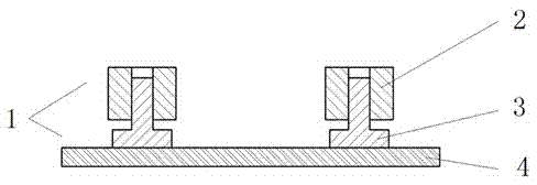
[0035] The MEMS device I2 is attached to the MEMS carrier wafer 4 , and the MEMS device II3 is interference-connected with the MEMS device I2 to form the MEMS 1 .

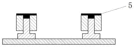
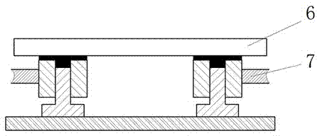
[0036]Wash the surface of the MEMS device I2 and the MEMS device II3 with alcohol or acetone, pre-coat the absorbing layer 5 on the back of the MEMS device I2 and the MEMS device II3, the thickness of the absorbing layer 5 is 0.1-0.15 mm, and there is enough viscosity to make The MEMS 1 will not fall off from the surface of the metallic glass 6; the MEMS 1 is adhered to the surface of the high-strength metallic glass 6 by using the viscosity of the absorbing layer 5, and the metallic glass 6 serves as the carrier for the MEMS 1 and the constraints of the laser shock layer; the metallic glass 6 carrying the micro-electro-mechanical s...


PUM

PropertyMeasurementUnit
Thicknessaaaaaaaaaa
Diameteraaaaaaaaaa
Pulse widthaaaaaaaaaa

Abstract

The invention relates to a dismounting method for micro electro-mechanical devices, in particular to a laser shock assisted dismounting method which uses expansion of plasma generated by laser shock and the mechanical effect of shock waves to separate the matched micro electro-mechanical devices and is suitable for dismounting and separating of the micro electro-mechanical devices. According to the laser shock assisted dismounting method for the micro electro-mechanical devices, the mechanical effect of the laser-induced shock waves is adopted, the micro electro-mechanical devices in a micro electro-mechanical system can be dismounted through non-contact force of the shock waves, contact scratches and damage to parts by conventional operation and the problem of being hard to dismount under the micro/nano-scale condition are avoided, shock pressure of the laser-induced shock waves is fully utilized to eject the micro electro-mechanical devices in the laser radiation directions, and the method is a brand-new micro electro-mechanical device dismounting method.

Description

technical field [0001] The invention relates to a disassembly method of micro-electromechanical devices, in particular to a method for separating mated micro-electro-mechanical devices by utilizing the expansion of plasma generated by laser shock and the mechanical effect of shock waves, and is suitable for disassembly and separation of micro-electro-mechanical devices. . Background technique [0002] MEMS has the characteristics of miniaturization, diversification, and microelectronics, and has advantages that traditional electromechanical systems cannot match. According to the size of the shape, MEMS can be divided into: 1-10mm micro machinery, 1μm-1mm micro Mechanics and 1nm-1μm nanomachines; at the scale that current microelectromechanical systems can achieve, the basic laws of the macroscopic physical world are still in effect, but with the continuous shrinking of devices or structures, the integration level is getting higher and higher, and the macroscopic Interferenc...

Claims


Application Information

Patent Timeline
IPC IPC(8): B23K26/00B23K26/18
CPCB23K26/00B23K26/18
Inventor 陈德张可新陈光国
Owner 重庆德秋建设工程有限公司
Why Eureka
Try Eureka