Laser deburring method and equipment

A deburring and laser technology, used in laser welding equipment, welding equipment, metal processing equipment, etc., can solve the problems of complex processing technology, low processing efficiency and high cost, and achieve simple structure, high processing efficiency and low cost. Effect

Active Publication Date: 2017-06-20
苏州贝亚敏光电科技有限公司
View PDF10 Cites 24 Cited by
  • Summary
  • Abstract
  • Description
  • Claims
  • Application Information

AI Technical Summary

Problems solved by technology

[0005] However, in the prior art, when laser equipment is used to deburr a workpiece, it usually changes the trajectory of the laser working head so that it can be deburred along the trajectory of the burr on the workpiece, which not only causes The complexity of the process, the processing efficiency is also low, and the cost is relatively high

Method used


Image

  • Laser deburring method and equipment
  • Laser deburring method and equipment
  • Laser deburring method and equipment

Examples


Embodiment Construction

[0039] The technical solutions of the present invention will be further described below in conjunction with the accompanying drawings and specific embodiments.

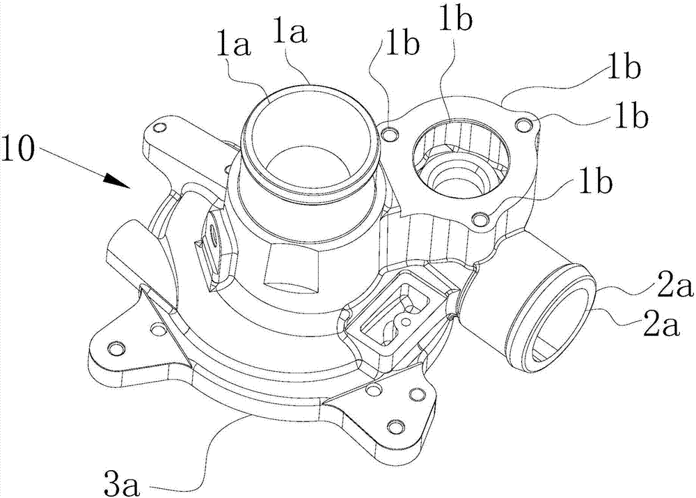
[0040] see figure 1 Shown is the turbine shell 10 that needs to be deburred in this embodiment. It is cast and has multiple processed surfaces. The position where two adjacent processed surfaces meet is often the position where burrs are generated and gathered. , the position where the two adjacent processing surfaces meet also forms the part that needs to be deburred, such as figure 1 1a, 1b, 2a, 3a in. The intersection lines between different processing surfaces also form the scanning trajectory of the laser beam scanning during laser processing and deburring. For example, the contour lines at 1a, 1b, 2a, and 3a are the corresponding scanning paths.

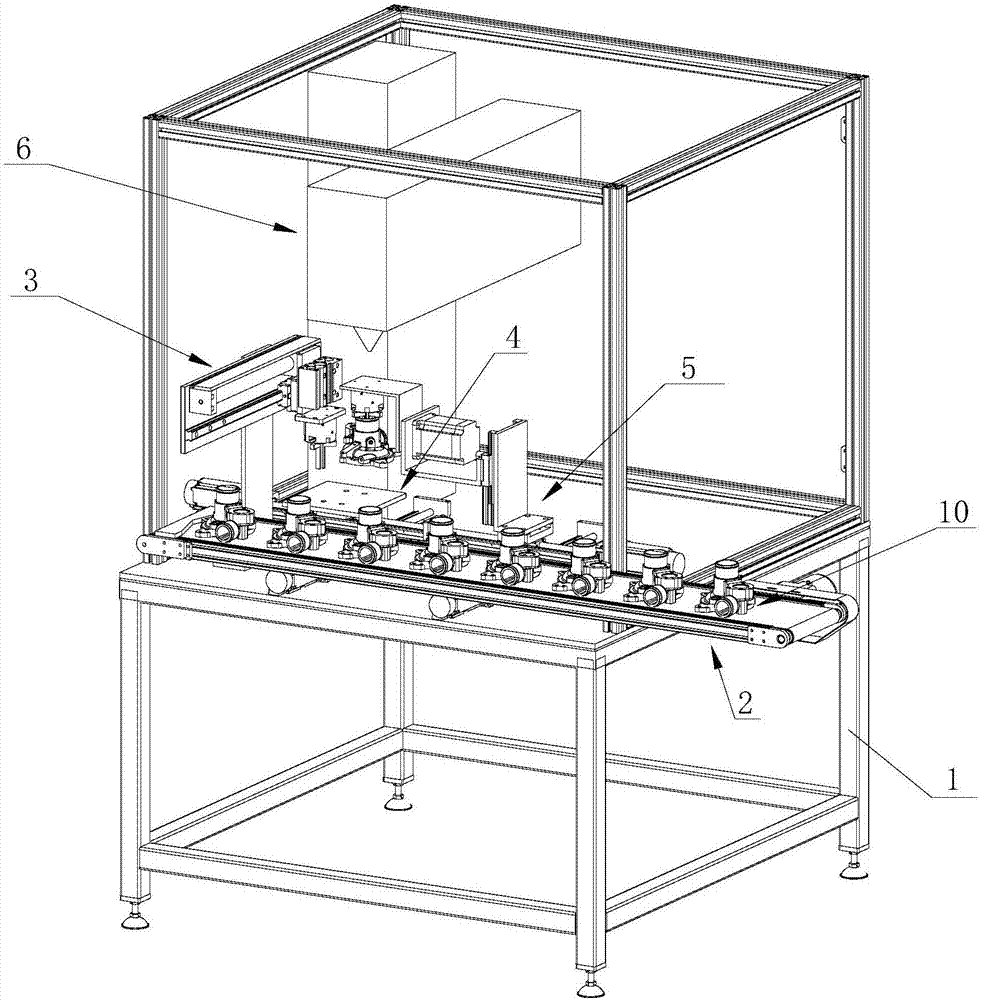
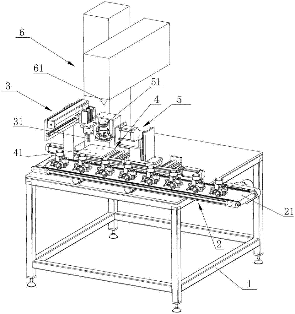
[0041] see figure 2 , image 3 Shown is the laser deburring equipment of this embodiment, which includes a base 1, a workbench 41 set on the base 1 for placing wo...


PUM


Abstract

The invention discloses a laser deburring method and equipment. The method comprises the steps: according to the three-dimensional image of a workpiece to be deburred, obtaining the contour graph of the part needing to be deburred on the workpiece, and then obtaining multiple scanning paths during scanning machining of a laser beam; then, according to the positions of the scanning paths on the workpiece, positioning the workpiece for many times, thus enabling different side parts of the workpiece to face to a laser working head, and therefore conducting laser scanning for deburring in order. In the process of laser deburring, the position of the laser working head does not need to change basically, only the workpiece to be deburred needs to be repositioned, and therefore the laser beam scans the side parts, facing to the laser working head, of the workpiece in order. During laser scanning, the workpiece is scanned according to the scanning paths obtained in advance. The method has high processing speed, is particularly suitable for large batches of parts for laser deburring, and can effectively improve the efficiency of laser deburring.

Description

technical field [0001] The invention relates to a laser deburring method and equipment. Background technique [0002] In the various processes of metal workpiece processing and forming, irregular metal parts such as various sharp corners and burrs often appear at the junction of the surface of the workpiece, that is, burrs. The existence of burrs is a kind of processing defect for the workpiece, which needs to be removed through the processing procedure of deburring. [0003] The process of deburring not only takes a lot of time, but also increases the processing cost of the workpiece. In order to achieve high-efficiency deburring on the workpiece, various deburring methods have also emerged. Common ones include roller grinding, high-temperature deburring, mechanical brush deburring, extrusion honing deburring, magnetic grinding, water jet deburring, etc. Burr and other methods. In recent years, with the rapid development of laser technology, the use of laser to remove ...

Claims


Application Information

Patent Timeline
Patent Type & Authority Applications(China)
IPC IPC(8): B23K26/361B23K26/70B23K26/082
CPCB23K26/082B23K26/361B23K26/702
Inventor 王明娣刘卫兵杨桂林刘凯陈天禹施克明
Owner 苏州贝亚敏光电科技有限公司
Why Eureka
Try Eureka