HG hot metal desulfurization device and desulfurization method thereof, and desulfurizer and slag remover

A technology of hot metal desulfurization and desulfurization agent, which is applied in the field of HG hot metal desulfurization device, desulfurizer and slag remover, can solve the problems of large consumption of desulfurizer, difficult removal of slag and easy resulfurization, difficult to reach deep desulfurization, etc., to reduce consumption and smelting time, strengthen dynamic conditions, and improve the effect of utilization

Inactive Publication Date: 2017-06-20
JIANGSU LIHUAI IRON AND STEEL CO LTD +1
View PDF4 Cites 2 Cited by
  • Summary
  • Abstract
  • Description
  • Claims
  • Application Information

AI Technical Summary

Problems solved by technology

However, because the desulfurization powder is added from the upper part of the ladle, the desulfurizer cannot completely enter the molten iron, and part of it floats on the slag surface or sticks to the stirring head, and is sucked away by the dust collector. There is a certain amount of waste, and it is difficult to reach deep desulfurization. The water temperature drop is large; the granular magnesium injection method can achieve deep desulfurization of molten iron, but after desulfurization, the slag is difficult to remove and easy to return to sulfur, and the consumption of desulfurizer is large, etc.

Method used


Image

  • HG hot metal desulfurization device and desulfurization method thereof, and desulfurizer and slag remover
  • HG hot metal desulfurization device and desulfurization method thereof, and desulfurizer and slag remover
  • HG hot metal desulfurization device and desulfurization method thereof, and desulfurizer and slag remover

Examples


Embodiment 1

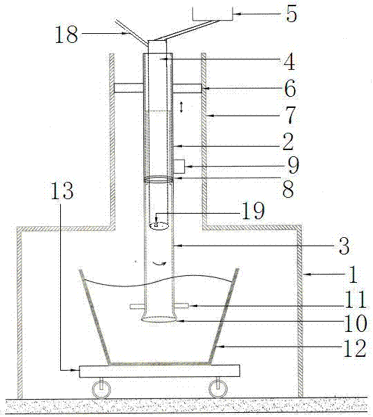
[0073] 1) After the molten iron ladle 12 to be desulfurized is advanced to the directly below the stirring tube 3, sampling and temperature measurement of the molten iron are carried out;

[0074] 2) After the temperature measurement is completed, the desulfurizer nozzle 4 moves down along the bracket 1 driven by the casing 2;

[0075] 3) When the lower nozzle 10 of the stirring tube 3 is about to contact the liquid surface of the molten iron in the ladle 12, open the gas valve of the nitrogen pipe 18, and the nitrogen flow rate is 100 Nm3 / h;

[0076] 3) The desulfurizing agent nozzle 4 continues to move downward along the support 1 under the drive of the casing 2 until the lower nozzle 10 of the stirring tube 3 and the stirring rod 11 extend into the molten iron in the ladle 12, and the insertion depth is 1.25 meters . Simultaneously start the rotary motor 9 to make the stirring tube 3 rotate, and rotate to the normal operating speed in the range of 70 to 100 r / min;

[0077...

Embodiment 2

[0089] 1) After the molten iron ladle 12 to be desulfurized is advanced to the directly below the stirring tube 3, sampling and temperature measurement of the molten iron are carried out;

[0090] 2) After the temperature measurement is completed, the desulfurizer nozzle 4 moves down along the bracket 1 driven by the casing 2;

[0091] 3) When the lower nozzle 10 of the stirring tube 3 is about to contact the liquid surface of the molten iron in the ladle 12, open the gas valve of the nitrogen pipe 18, and the nitrogen flow rate is 110 Nm3 / h;

[0092] 3) The desulfurizing agent nozzle 4 continues to move downward along the support 1 under the drive of the casing 2 until the lower nozzle 10 of the stirring tube 3 and the stirring rod 11 extend into the molten iron in the ladle 12, and the insertion depth is 1.35 meters . Simultaneously start the rotating motor 9 to make the stirring tube 3 rotate, and rotate to the normal operating speed in the range of 80 ~ 110 r / min;

[009...

Embodiment 3

[0105] 1) After the molten iron ladle 12 to be desulfurized is advanced to the directly below the stirring tube 3, sampling and temperature measurement of the molten iron are carried out;

[0106] 2) After the temperature measurement is completed, the desulfurizer nozzle 4 moves down along the bracket 1 driven by the casing 2;

[0107] 3) When the lower nozzle 10 of the stirring tube 3 is about to contact the liquid surface of the molten iron in the ladle 12, open the gas valve of the nitrogen pipe 18, and the nitrogen flow rate is 95 Nm3 / h;

[0108] 3) The desulfurizing agent nozzle 4 continues to move downward along the support 1 under the drive of the casing 2 until the lower nozzle 10 of the stirring tube 3 and the stirring rod 11 extend into the molten iron in the ladle 12, and the insertion depth is 1.3 meters . Simultaneously start the rotary motor 9 to make the stirring tube 3 rotate, and rotate to the normal operating speed in the range of 90 to 120 r / min;

[0109] ...


PUM

PropertyMeasurementUnit
particle diameteraaaaaaaaaa

Abstract

The invention discloses a HG hot metal desulfurization device and desulfurization method thereof, and a desulfurizer and a slag remover. A nozzle of the desulfurizer is formed in a support, the nozzle of the desulfurizer is fixed inside a sleeve, the sleeve is movably connected to the support in up and down direction, the lower part of the sleeve is rotationally connected with a stirred tube, one end of the nozzle of communicates with desulfurizer a stock bin of the desulfurizer, the other end of the nozzle of the desulfurizer communicates with the lower nozzle of the stirred tube, a nitrogen gas tube is in connection with the nozzle of the desulfurizer, the outlet direction of the nitrogen gas tube points to the lower nozzle of the stirred tube, a stirred tube is located at outside of the tube wall under the position of the lower part of the nozzle and fixed with a stirred rod , and the stirred tube is connected to a rotating motor fixed on the outside wall of the sleeve in a transmission mode. According to the structure of the HG hot metal desulfurization device, not only the dynamic property conditions of desulfurization is strengthened, but also a deep, complete, and full mixing of the desulfurizer with the hot mental can be made and desulfurization by reaction, thus utilization ratio of desulfurizer is improved, waste of desulfurizer is avoided, and in addition, nodulation of the stirring device is prevented.

Description

technical field [0001] The invention relates to the field of hot metal pre-desulfurization production, in particular to a HG hot metal desulfurization device, a desulfurization method thereof, a desulfurizer and a slag remover. Background technique [0002] With the development of special steel, some special steel types have higher and higher requirements for residual sulfur in molten steel, and the deep desulfurization treatment of molten iron entering the furnace has become a necessary link in the steelmaking production process. At present, the two main methods of hot metal desulfurization are granular magnesium injection desulfurization and KR stirring desulfurization. [0003] Comparing the two desulfurization processes: the KR method has good desulfurization dynamic conditions and high desulfurization rate, and the desulfurizer is cheap and safe. However, because the desulfurization powder is added from the upper part of the ladle, the desulfurizer cannot completely en...

Claims


Application Information

Patent Timeline
Patent Type & Authority Applications(China)
IPC IPC(8): C21C7/064
CPCC21C7/064C21C7/0006C21C7/0037C21C7/0645
Inventor 印传磊杨丽梅陈少慧林鹏田春阳郑力宁马建超翟万里金磊
Owner JIANGSU LIHUAI IRON AND STEEL CO LTD
Why Eureka
Try Eureka