
A non-embedded intelligent speed bump and its working method

A speed bump, non-embedded technology, applied in the field of non-embedded intelligent speed bump, can solve the problems of difficult maintenance, inconvenient use and popularization of intelligent speed bump, etc., achieves accurate adjustment, is conducive to controlling vehicle speed, and ensures safe driving. Effect

Active Publication Date: 2019-01-08
NANJING UNIV OF AERONAUTICS & ASTRONAUTICS
View PDF6 Cites 0 Cited by
  • Summary
  • Abstract
  • Description
  • Claims
  • Application Information

AI Technical Summary

Problems solved by technology

What is still insufficient is that most of the existing smart speed bumps need to dig the road for landfill installation, which brings great inconvenience to the use and popularization of smart speed bumps, and also makes later maintenance particularly difficult

Method used


Image

  • A non-embedded intelligent speed bump and its working method
  • A non-embedded intelligent speed bump and its working method

Examples


Embodiment Construction

[0032] The technical solutions of the embodiments of the present invention will be described in detail below in conjunction with the accompanying drawings.

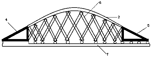
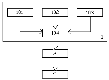
[0033] like figure 1 As shown, a non-embedded intelligent deceleration belt according to the embodiment of the present invention includes: a control processing device 1, a crawler type deceleration belt body 2, a driving motor 3, a fixed frame 4, a sliding frame 5, and n groups of fork-type push-pull components 6 , The top surface is provided with the base 7 of slide rail. Wherein, n is an integer greater than 3, such as 5, 7 or 10. The selection of the n value can be determined according to the length of the crawler type deceleration belt body 2 .

[0034] N sets of fork-shaped push-pull assemblies 6 are arranged parallel to each other. like figure 1 As shown, the fork-type push-pull assembly 6 includes multiple sets of slanting rods, and each set of slanting rods includes two slanting rods. Two oblique rods are arr...


PUM


Abstract

The invention discloses a non-embedded intelligent deceleration strip. The non-embedded intelligent deceleration strip comprises a control processing device, a crawler-type deceleration strip body, a driving motor, a fixing frame, a sliding frame, n fork type push-pull assemblies and a base; the deceleration strip body is located above the fork type push-pull assemblies, and the top ends of inclined rods of the fork type push-pull assemblies are rotatably connected with the deceleration strip body; and a first pulley is mounted at the bottom end of the inclined rod of each fork type push-pull assembly; the fixing frame and the sliding frame are located at the two ends of the deceleration strip body; the fixing frame is connected with one ends of the fork type push-pull assemblies rotatably, and the sliding frame is connected with the other ends of the fork type push-pull assemblies rotatably; second pulleys are mounted at the bottom end of the sliding frame, and the first pulleys and the second pulleys are embedded in a sliding rail; the driving motor is fixed to the base, and the driving motor is connected with the sliding frame; and the signal output end of the control processing device is connected with the signal input end of the driving motor. According to the non-embedded intelligent deceleration strip, excavation of the road surface for embedding is not needed, later maintenance is convenient, and a vehicle can be decelerated more accurately.

Description

technical field [0001] The invention belongs to the field of road traffic, and in particular relates to a non-embedded intelligent speed bump and a working method thereof. Background technique [0002] With the increasing number of vehicles, the increasingly serious traffic congestion and the frequent occurrence of traffic accidents, the research on intelligent transportation systems has been paid more and more attention. Internationally, the United States, Japan, Britain and other countries are in a leading position in this field. For example, the U.S. Department of Transportation released the Intelligent Transportation Strategic Plan (2015-2019) in August 2015, focusing on building safer vehicles and roads. [0003] In China, intelligent speed bumps are also one of the research hotspots of intelligent transportation. In 2010, Fuzhou University proposed an intelligent road speed bump based on a radar speedometer. However, the cost of this solution is relatively high, and...

Claims


Application Information

Patent Timeline
Patent Type & Authority Patents(China)
IPC IPC(8): E01F9/529
Inventor 许娟刘颖窦山岳罗有成易奕
Owner NANJING UNIV OF AERONAUTICS & ASTRONAUTICS
Learn More