
Construction method of steel pipe support structure for foundation pit surrounded by ground connection wall

A technology of steel pipe support and construction method, which is applied in basic structure engineering, excavation, building construction, etc., can solve the problems of long construction period, high engineering cost, collapse of groove wall, etc., so as to increase the tensile and shear resistance and shorten the construction period. , make the effect of easy installation

Active Publication Date: 2019-02-15
SHANGHAI GEOLOGICAL CONSTR
View PDF6 Cites 0 Cited by
  • Summary
  • Abstract
  • Description
  • Claims
  • Application Information

AI Technical Summary

Problems solved by technology

However, its construction is greatly affected by geological conditions and the surrounding environment. During the construction process, the groove wall is prone to collapse, the groove is deflected, and there may be leakage at the joint when the main body of the foundation pit is excavated.
In the face of tight construction schedules, various and complex underground pipelines, and difficult traffic relief, it is difficult to ensure the smooth completion of construction tasks under the condition of safety and quality assurance
[0003] In the existing deep foundation pit engineering, the steel support end is generally used to support the steel backing plate welded with the underground diaphragm wall. The steel support end is not directly buried in the underground diaphragm wall structure, resulting in the steel support end The shear capacity is greatly reduced, and the reinforced concrete support process is cumbersome, the construction period is long, and the project cost is high

Method used


Image

  • Construction method of steel pipe support structure for foundation pit surrounded by ground connection wall
  • Construction method of steel pipe support structure for foundation pit surrounded by ground connection wall
  • Construction method of steel pipe support structure for foundation pit surrounded by ground connection wall

Examples


Embodiment Construction

[0038] Specific embodiments of the present invention will be described in detail below in conjunction with the accompanying drawings.

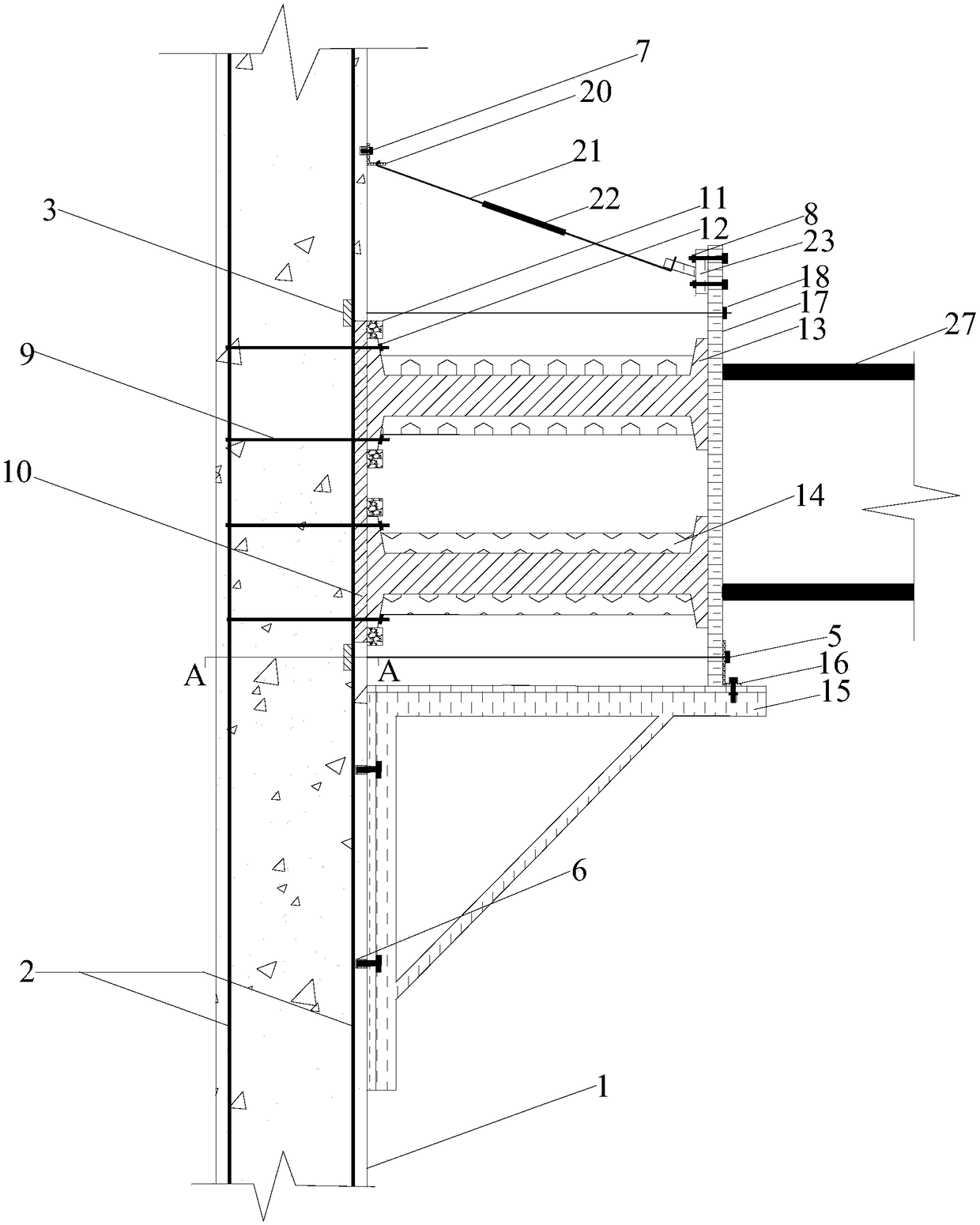
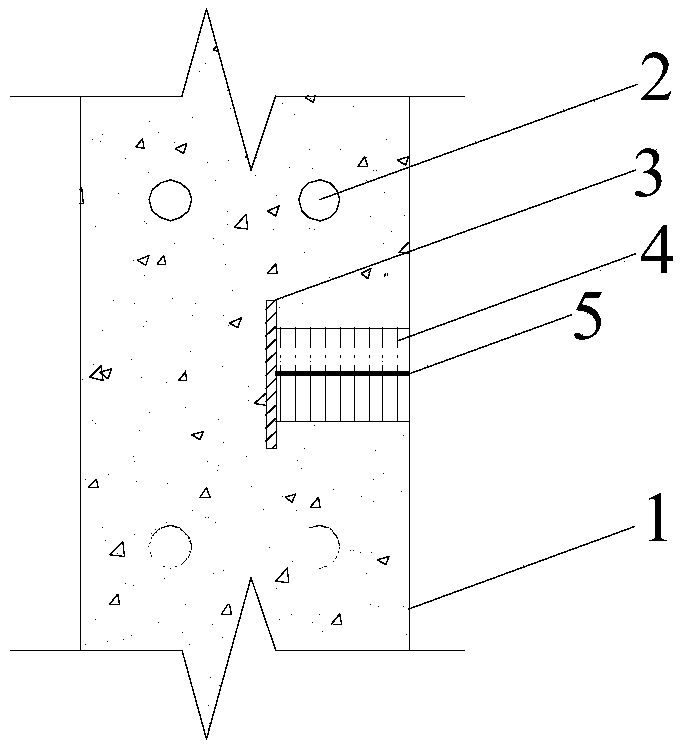
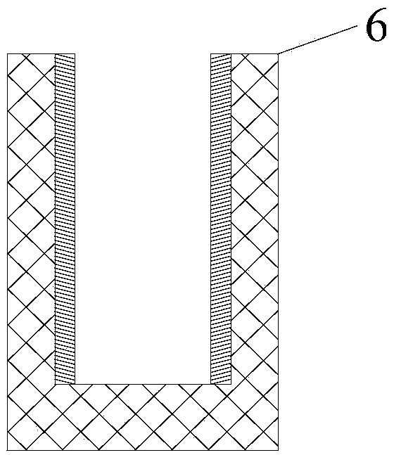
[0039] figure 1 It is a schematic diagram of the steel pipe support structure and construction method of the wall surrounding the foundation pit of the present invention, figure 2 yes figure 1 Sectional view along line A-A, image 3 is a schematic diagram of the embedded connection sleeve; Figure 4 is a schematic diagram of the bolt; Figure 5 is the schematic diagram of the nut; Figure 6 It is a schematic diagram of U-shaped fixing bars; Figure 7 is the schematic diagram of the embedded end plate; Figure 8 It is a schematic diagram of an L-shaped movable end plate; Figure 9 is a schematic diagram of the panel; Figure 10 is the schematic diagram of the anchorage; Figure 11 is the schematic diagram of the fixture; Figure 12 It is a schematic diagram of an L-shaped hanging board; Figure 13 is a schematic diagram of a movable...


PUM


Abstract

The invention discloses a construction method for an underground diaphragm wall containment foundation pit steel pipe supporting structure. The underground diaphragm wall containment foundation pit steel pipe supporting structure mainly comprises an underground diaphragm wall, underground continuous wall main ribs, embedded anchor cable fixing ends, anchor cables, anchor cable protection pipes, embedded connecting sleeves, U-shaped fixing ribs, an embedded end plate, positioning steel plates, joint steel, ribbed rib plates, a supporting bracket, a batten plate, a pull rod with a hook and a steel support. The construction method mainly includes the steps of grooving construction, reinforcement cage manufacturing, concrete pouring, chiseling of a part of the underground diaphragm wall, joint connecting and the like. A connecting joint of the construction method has the beneficial effects that the shear strength is high, connecting is convenient and fast, and structural steel can be recycled and reused; and the construction method achieves the purposes that the construction period is shortened, and the construction cost is reduced.

Description

technical field [0001] The invention relates to the field of deep foundation pit engineering, in particular to a construction method of a steel pipe support structure for foundation pits surrounded by ground connection walls. Background technique [0002] With the rapid development of my country's national economy and technology, the construction of public infrastructure is the inevitable result of the development of formal science and technology. my country's subway construction has made rapid development since the 1990s. The underground diaphragm wall is a form of enclosure structure often used in the construction of urban subway stations. The construction of the underground diaphragm wall is widely used due to its advantages of no noise, no vibration, and little impact on surrounding buildings. At the same time, it has good vertical anti-leakage Protective measures are widely used in the main enclosure structure engineering of the station. However, its construction is gr...

Claims


Application Information

Patent Timeline
Patent Type & Authority Patents(China)
IPC IPC(8): E02D17/04E02D17/20E04G21/00
CPCE02D17/04E02D17/20E04G21/00
Inventor 王新泉
Owner SHANGHAI GEOLOGICAL CONSTR
Learn More