
Pit-in-pit novel framework supporting system and construction method thereof

A construction method and pit-in-pit technology, which is applied in the direction of formwork/formwork/work frame, wine cellar, building components, etc., can solve the problem that the bottom of the pit in the pit cannot be vibrated, and the surface, floating, and the height difference in the pit can be solved. Insufficient and other problems, to achieve the effect of ensuring the plane size and the flatness of the side wall, easy operation and simple construction

Inactive Publication Date: 2017-06-20
ZHONGTIAN CONSTR GROUP
View PDF4 Cites 4 Cited by
  • Summary
  • Abstract
  • Description
  • Claims
  • Application Information

AI Technical Summary

Problems solved by technology

[0005] In order to overcome the shortcomings of the traditional construction method, the present invention provides a new type of pit-in-pit formwork system and its construction method, which effectively solves the problems of floating up of the pit-in-pit box film, insufficient height difference of the pit-in-pit, and inability of the concrete on the bottom of the pit-in-pit. Problems such as vibration and surface closing not only ensure the construction quality of the elevator shaft and the bottom plate of the water collection well, but also greatly reduce the quality hidden dangers such as water leakage in the later stage of this part. At the same time, the construction process of the pit-in-pit support system is simplified, and the bottom concrete pouring method

Method used


Image

  • Pit-in-pit novel framework supporting system and construction method thereof
  • Pit-in-pit novel framework supporting system and construction method thereof

Examples


Embodiment Construction

[0021] The present invention will be further described below in conjunction with the accompanying drawings and embodiments.

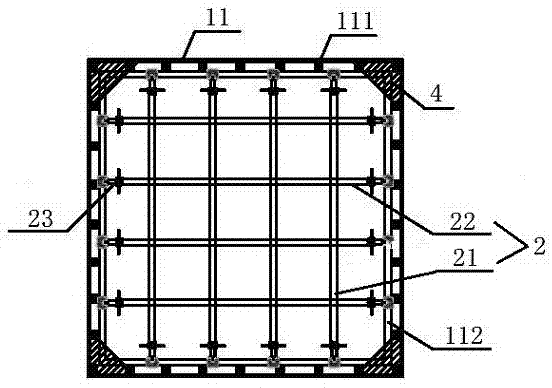
[0022] Such as figure 1 , 2 As shown, a new type of pit-in-pit formwork support system in this embodiment mainly includes a box mold 1 and a support 2. The box mold 1 is a box-shaped formwork with an upper opening, consisting of a side formwork 11 and a bottom formwork 12. The support 2 includes a longitudinal support 21 and a transverse support 22 . The bottom template 12 is composed of four strip templates 121 with a width of 200 mm, which are circularly spliced ​​to form a hollow bottom template with an opening in the middle. The bottom formwork 12 is provided with square wood 122, and the side formwork 11 is provided with vertical inner corrugation 111 and horizontal outer corrugation 112. The vertical inner corrugation 111 adopts high-quality square wood, and the horizontal outer corrugation 112 adopts double steel pipes. The support 2 is compos...


PUM


Abstract

The invention provides a pit-in-pit novel framework supporting system. The pit-in-pit novel framework supporting system includes a box framework and a supporting structure; the box framework is a box-shaped template having an upper opened part and includes side templates and a bottom template; the supporting structure includes vertical supports and horizontal supports; the bottom template is formed by jointing bar-shaped templates so as to form a hollow bottom template having an opened center; positioning steel ribs of a pit-in-pit bottom plate are arranged under the side templates; and triangular reinforcement plates are arranged on internal corners of the box framework. The construction method includes the following steps: 1, manufacturing the side templates and the bottom template, and jointing the templates to form the opened box framework; 2, arranging the box framework; 3 arranging the supporting structure; and 4, pouring concrete, performing vibration, and performing surface finishing. The beneficial effects of the invention are that the problem that the box framework floats upward while the concrete is poured can be effectively saved; a weighting measure can be avoided; trash and gathered water in a pit-in-pit part can be timely cleaned through an opening of the bottom template; the positioning ribs can control the elevation height of the pit-in-pit bottom plate; basement bottom plates are prevented from water leakage; and the construction quality of deep parts of the pit-in-pit can be effectively improved.

Description

technical field [0001] The invention relates to the technical field of large-volume concrete construction for a basement floor, in particular to a new type of pit-in-pit formwork support system and a construction method thereof. Background technique [0002] With the gradual increase of high-rise buildings, the application of large-volume concrete foundation slabs and ultra-deep and ultra-large pits is becoming more and more frequent. The construction of the pit-in-pit part is very difficult, especially due to the unreasonable traditional formwork support system, it is easy to cause a series of problems such as the floating of the pit bottom, the inclination of the formwork support system, the lack of compactness of the concrete pouring of the pit-in-pit floor, and water leakage. It is extremely unfavorable to ensure the construction quality of the floor of the basement, especially the floor of the elevator shaft and the water collection well, and the construction quality pr...

Claims


Application Information

Patent Timeline
Patent Type & Authority Applications(China)
IPC IPC(8): E04G13/00E04B1/00
CPCE04B1/0007E04G13/00
Inventor 包纯南吴宁青陈滨雄刘秋媛
Owner ZHONGTIAN CONSTR GROUP
Learn More