
Electronic cannon head and manufacturing method

A cannon head and electronic technology, which is applied in the field of electronic cannon, can solve the problems of low success rate of working electrode discharge, achieve the effects of simple and convenient debugging, lower production process requirements, and higher yield

Active Publication Date: 2018-07-10
LIAONING JIDIAN POLYTECHNIC
View PDF4 Cites 0 Cited by
  • Summary
  • Abstract
  • Description
  • Claims
  • Application Information

AI Technical Summary

Problems solved by technology

[0005] The embodiment of the present invention provides an electronic nozzle and a manufacturing method to solve the problem in the prior art that the discharge success rate of the working electrode caused by the ignition electrode is low

Method used


Image

  • Electronic cannon head and manufacturing method
  • Electronic cannon head and manufacturing method
  • Electronic cannon head and manufacturing method

Examples


Embodiment Construction

[0031] The following will clearly and completely describe the technical solutions in the embodiments of the present invention with reference to the accompanying drawings in the embodiments of the present invention. Obviously, the described embodiments are only some, not all, embodiments of the present invention. Based on the embodiments of the present invention, all other embodiments obtained by persons of ordinary skill in the art without making creative efforts belong to the protection scope of the present invention.

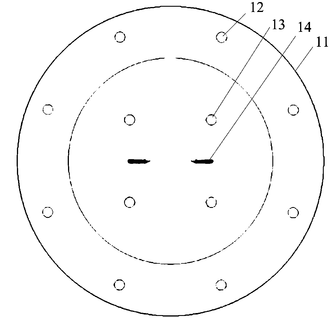
[0032] figure 1 It is a schematic structural diagram of a traditional electronic gun head provided by the embodiment of the present invention. Such as figure 1 As shown, the traditional electronic gun head includes: a traditional gun head body 11 , a traditional gun head working electrode 12 , a traditional gun head transition electrode 13 and a traditional gun head firing electrode 14 .

[0033] It should be noted that the discharge success rate of the work...


PUM


Abstract

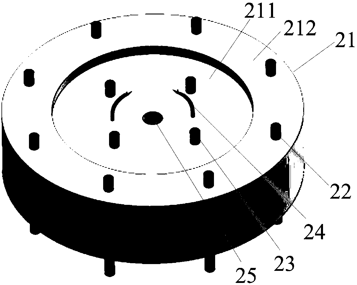
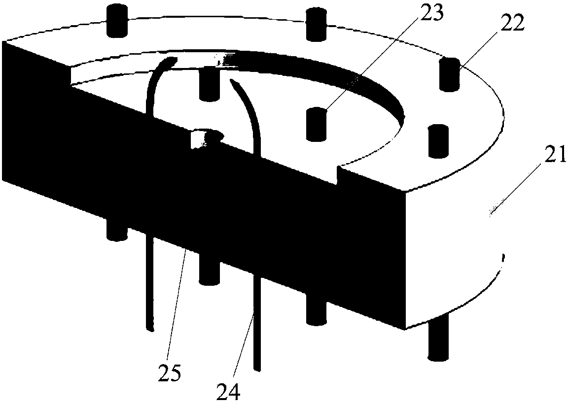
The invention discloses an electronic gun head and a manufacturing method, and relates to the technical field of electronic guns. The electronic gun comprises a gun head body, a working electrode, transition electrodes, ignition electrodes and blind holes; connecting lines of four transition electrodes form a rectangle; two ignition electrodes are respectively distributed at the middle parts of two long edges of the rectangle; the blind holes are distributed at the middle part in the rectangle; permanent magnets are buried in the blind holes; distances from the top surfaces of the permanent magnets to the inner top surfaces of circular grooves are 3-8 mm; and epoxy resins are poured on the top surfaces of the permanent magnets. The electronic gun head uses a magnetic force effect of neodymium-iron-boron permanent magnets for lengthening arcs generated by the ignition electrodes to gather in the center position of the gun head body, so that air between the transition electrodes is effectively ionized, the arcs of the transition electrodes are smoothly struck, the discharge of the working electrodes is caused, and the ignition is successful; and the discharge between the transition electrodes and the working electrodes is ignited by the arcs of the ignition electrodes to generate air detonation, so that the ignition success rate reaches 100%.

Description

technical field [0001] The invention relates to the technical field of electronic guns, and more specifically relates to an electronic gun head and a manufacturing method. Background technique [0002] The electron gun uses a higher voltage to discharge instantaneously between multiple working electrodes, causing the temperature of the air around the electrodes to rise suddenly, producing air popping sound and visible light. The discharge between the working electrodes requires another small electrode discharge with a higher voltage to initiate (ie, the ignition electrode). Due to space and natural conditions (such as changes in wind, temperature and humidity, etc.), the arc generated by the ignition electrode discharge may deviate from the center, or the length of the arc is not enough, etc., the degree of ionized air of the ignition electrode cannot meet the arc of the transition electrode, so the success rate of triggering the discharge of the working electrode is low. Th...

Claims


Application Information

Patent Timeline
Patent Type & Authority Patents(China)
IPC IPC(8): F42B12/02
CPCF42B12/02
Inventor 许连阁郭海林于晓云夏金伟李震
Owner LIAONING JIDIAN POLYTECHNIC
Learn More