L-section type concentrating photovoltaic battery chip

A concentrating photovoltaic and battery technology, applied in the field of solar photovoltaic power generation, can solve the problem of reducing the effective light-receiving area of ​​the concentrating photovoltaic cell chip, wasting the substrate material of the concentrating photovoltaic cell base layer, reducing the power generation efficiency of the concentrating photovoltaic system, etc. problems, to achieve the effect of no reduction in power generation efficiency, reduction of production costs, and reduction of consumption

Inactive Publication Date: 2017-06-20
成都聚合追阳科技有限公司
View PDF2 Cites 1 Cited by
  • Summary
  • Abstract
  • Description
  • Claims
  • Application Information

AI Technical Summary

Problems solved by technology

But in practical application, the negative electrode layer on the concentrated photovoltaic cell chip is always smaller than the base material layer of the concentrated photovoltaic cell, because the base material on the base material layer of the concentrated photovoltaic cell is relatively expensive (a base material with a size of one square centimeter Material material is about 50 yuan), which greatly wastes the base material of the base material layer of the concentrating photovoltaic cell; in addition, with the increase of the lens multiple, the electrodes on the light-receiving surface of the concentrating photovoltaic cell chip will increase. Large, this will reduce the effective light-receiving area of ​​the concentrating photovoltaic cell chip, and because the converging rate of the lens cannot reach 100%, outside the effective light-receiving surface (especially the concentrated light on the electrode of the concentrating photovoltaic cell chip) The concentrated light cannot be converted into electricity, which will greatly reduce the power generation efficiency of the concentrated photovoltaic system

Method used


Image

  • L-section type concentrating photovoltaic battery chip
  • L-section type concentrating photovoltaic battery chip

Examples


Embodiment Construction

[0014] The present invention will be further described below in conjunction with the accompanying drawings.

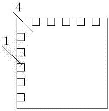
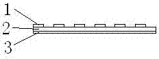
[0015] A kind of L segment type concentrator photovoltaic cell chip, such as Figure 1~2 As shown, it includes a negative electrode segment layer 1, a concentrating photovoltaic cell base material layer 2, a positive electrode layer 3 and an effective area 4. One side of the concentrating photovoltaic cell base material layer 2 is covered with a negative electrode segment layer 1, and the other side is covered with The upper positive electrode layer 3, the part other than the negative electrode segment layer 1 is an effective area 4, the negative electrode segment layer 1 is a flat L-shaped shape, two of the negative electrode segment layer and the concentrating photovoltaic cell substrate layer The two adjacent end faces are completely overlapped, so that the substrate layer of the concentrating photovoltaic cell is fully utilized, thereby achieving the purpose of sav...


PUM


Abstract

The invention relates to an L-section type concentrating photovoltaic battery chip, and belongs to the technical field of solar photovoltaic power generation. The L-section type concentrating photovoltaic battery chip comprise a negative electrode section layer, a concentrating photovoltaic battery base material layer, a positive electrode layer and an active area; one surface of the concentrating photovoltaic battery base material layer is coated with the negative electrode section layer while the other surface is coated with the positive electrode layer; and the part except the negative electrode section layer is the active area. By adoption of the battery chip, the usage amount of the concentrating photovoltaic battery base material can be greatly reduced, so that the manufacturing cost of the concentrating photovoltaic battery chip can be lowered; along with the increasing of concentrating times of a lens, the electrode section width can be improved; meanwhile, by adjusting an electrode into the electrode section, the unchanged property of the light-receiving area is maintained, and the overall power generation efficiency of the concentrating photovoltaic system is not reduced; and by improving the width of the negative electrode section, it is ensured that after the amplifying times of the lens is improved, the concentrating light can be converted into high-current electric energy which can be smoothly conducted through the negative electrode section.

Description

technical field [0001] The invention relates to a photovoltaic power generation component, in particular to an L-segment concentrating photovoltaic cell chip, which belongs to the technical field of solar photovoltaic power generation. Background technique [0002] Generally, the main benefit sought by concentrated photovoltaic power generation systems is to obtain high-density sunlight concentrated from Fresnel lenses on the effective area of ​​concentrated photovoltaic cell chips. The higher the multiple of the lens, the higher the density of sunlight obtained, the fewer concentrated photovoltaic cell chips used on the same area, and the lower the power generation cost per unit area. [0003] At present, the focal spot gathered from the Fresnel lens is usually square, and the shape and size of the focal spot are usually consistent with the shape and size of the concentrated photovoltaic cell chip, so that the focal spot gathered by the Fresnel lens can be completely conve...

Claims


Application Information

Patent Timeline
Patent Type & Authority Applications(China)
IPC IPC(8): H01L31/0224H01L31/054
CPCY02E10/52H01L31/022425H01L31/054
Inventor 李利平
Owner 成都聚合追阳科技有限公司
Why Eureka
Try Eureka