Commercial furnace remote monitoring system

A remote monitoring system and stove technology, applied in transmission systems, household appliances, household stoves/stoves, etc., can solve problems such as troubleshooting, low gas utilization, and inability to sense and cut off in time, so as to accurately respond to emergencies Effect

Pending Publication Date: 2017-06-20
上海郅洪节能科技有限公司
View PDF5 Cites 1 Cited by
  • Summary
  • Abstract
  • Description
  • Claims
  • Application Information

AI Technical Summary

Problems solved by technology

[0004] However, there are still major problems in the actual use of commercial stoves. For example, the utilization rate of gas in the combustion process of commercial stoves is low and the fuel loss is large; Without real-time feedback, it is impossible to know the degree of use of the stove and whether it has achieved the expected effect in a timely manner. This situation also makes it impossible to troubleshoot the source of the fault in a timely manner when a commercial stove fails; even in an emergency, it cannot Timely sensing and cutting off the fault source to avoid adverse consequences

Method used


Image

  • Commercial furnace remote monitoring system

Examples


Embodiment 1

[0023] Example 1: User Control

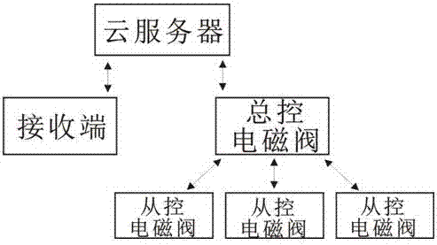
[0024] The sensor is responsible for the monitoring of fuel delivery flow and stove failure detection, and uploads the corresponding data to the cloud server in real time through the information acquisition board. The cloud server performs digital calculations based on the original flow data stored by itself, and feeds back the results to the receiving end at regular intervals , the receiving end can directly send a control command to the cloud server according to its own adjustment needs, and the cloud server will judge whether the control command is a white command module after the identity recognition is successful, and if it is a white command module, it will directly issue a control command to the master control solenoid valve Command, and then the command is transmitted from the master control solenoid valve to the slave control solenoid valve to realize the direct control of the receiving end on its own fuel. If it is an inquiry command, ...

Embodiment 2

[0025] Embodiment 2: Supplier or manager control

[0026] The sensor is responsible for the monitoring of fuel delivery flow and stove failure detection, and uploads the corresponding data to the cloud server in real time through the information acquisition board. Feedback, the supplier performs fuel delivery control according to the feedback, and directly performs the control operation of the master control solenoid valve on the cloud server. At this time, the control is regarded as a white command module, and the cloud server issues commands to the master control solenoid valve, and then the master control The solenoid valve transmits commands to the slave control solenoid valve to realize the switching of the slave control solenoid valve, that is, to realize the control of fuel delivery at the supply end.


PUM


Abstract

The invention provides a commercial furnace remote monitoring system, which comprises a cloud server, a receiving end, a master solenoid valve, slave solenoid valves and sensors. The cloud server is wirelessly connected with the receiving end and the master solenoid valve; the master solenoid valve is arranged in region control formed by one or more groups of commercial furnaces; the slave solenoid valves are arranged at the tail ends of fuel conveying lines of each group of commercial furnaces; and the sensors are arranged on the furnaces respectively. The beneficial effects are that the system adopts a multilevel control mode; on one hand, a supplier or an administrator can start a master control function to realize remote control of individual furnaces or all furnaces, and on the other hand, a user can send a control command to a master controller through the cloud server so as to realize fuel control directly or indirectly through the master controller; and the system not only realizes balance of fuel whole regulation and branch regulation very well, but also can monitor use state of each furnace in real time so as to deal with sudden incidents timely and accurately.

Description

technical field [0001] The invention relates to the field of commercial stove material supply, in particular to a remote monitoring system for commercial stoves. [0002] technical background [0003] At present, stoves are widely used because of their many advantages. Commercial stoves, as a kind of stoves, also have many advantages of stoves, which are manifested in: uniform furnace temperature, uniform heating of workpieces, large loading capacity, and high productivity. , preheating, good insulation performance of the furnace body, energy saving, production cost reduction, simple operating conditions, good environmental protection benefits, etc. [0004] However, there are still major problems in the actual use of commercial stoves. For example, the utilization rate of gas in the combustion process of commercial stoves is low and the fuel loss is large; Without real-time feedback, it is impossible to know the degree of use of the stove and whether it has achieved the exp...

Claims


Application Information

Patent Timeline
Patent Type & Authority Applications(China)
IPC IPC(8): H04L29/08G05B19/418F24C3/12
CPCH04L67/025H04L67/10H04L67/12G05B19/418F24C3/12Y02P90/02
Inventor 唐智洪
Owner 上海郅洪节能科技有限公司
Why Eureka
Try Eureka