
Real-time verification device and method for patient placement in radiation therapy

A real-time verification, radiation therapy technology, applied in radiation therapy, X-ray/γ-ray/particle irradiation therapy, treatment and other directions, can solve the problem of inability to perform real-time verification of positioning, complex algorithm operation steps, affecting the therapeutic effect of patients, etc. problems, to achieve the effect of reducing the risk of irradiation, rapid setup guidance and verification, and reducing treatment costs

Active Publication Date: 2017-06-23
INST OF MODERN PHYSICS CHINESE ACADEMY OF SCI
View PDF3 Cites 20 Cited by
  • Summary
  • Abstract
  • Description
  • Claims
  • Application Information

AI Technical Summary

Problems solved by technology

The disadvantage is that the imaging is not clear enough, or it will bring extra radiation dose to the normal tissue of the patient, which may cause complications in the patient
Colleagues need a long time for registration and fusion to verify the patient's positioning after obtaining the images, and real-time positioning verification cannot be achieved
[0004] Therefore, the problem existing in the existing technology is that the patient will receive an additional radiation dose during the imaging process, which increases the risk of disease in the normal tissue of the patient; at the same time, the algorithm operation steps for positioning verification using the obtained images are relatively complicated and difficult. To achieve real-time setup verification, which may affect the therapeutic effect of patients

Method used


Image

  • Real-time verification device and method for patient placement in radiation therapy
  • Real-time verification device and method for patient placement in radiation therapy
  • Real-time verification device and method for patient placement in radiation therapy

Examples


Embodiment Construction

[0026] Below in conjunction with the best examples shown in the accompanying drawings for further details:

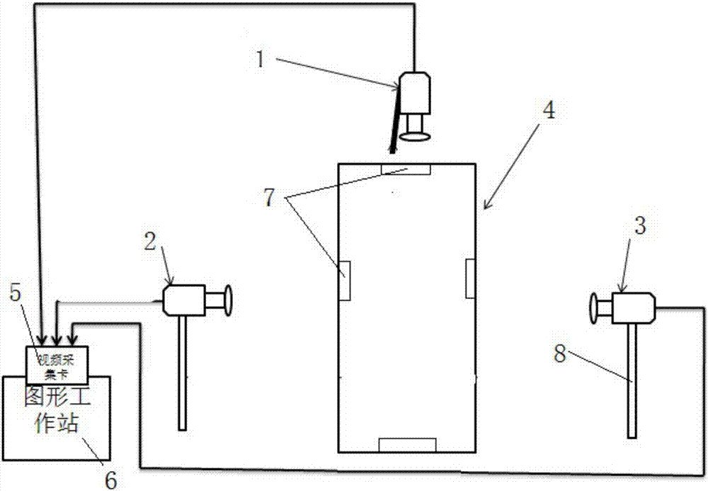
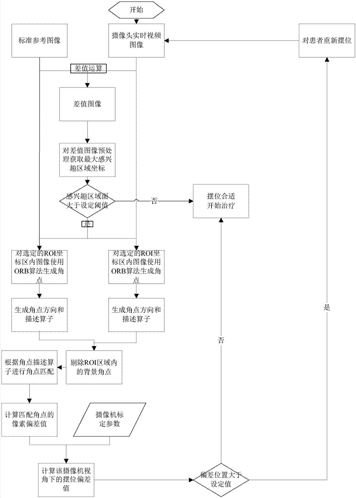
[0027] Such as figure 1 and 2 As shown, the real-time verification device for patient positioning in radiation therapy is characterized by including a first optical camera 1, a second optical camera 2 and a third optical camera arranged around the treatment couch 4 in the treatment room Cameras 3, each optical camera is installed on the corresponding bracket 8, wherein the first optical camera 1 is arranged facing the front of the treatment bed, and the second optical camera 2 and the third optical camera 3 are respectively arranged on both sides of the treatment bed 4 , three optical cameras are connected to the video capture card 5 through video lines, the video capture card 5 is installed on the graphics workstation 6, and the video calibration board 7 is arranged on the treatment bed 4 corresponding to the patient's head, feet, left and right sides Above, the vide...


PUM


Abstract

The invention relates to the technical field of patient location verification in a radiation therapy process, and particularly relates to a real-time verification device and method for patient placement in radiation therapy. The device comprises a first optical camera, a second optical camera and a third optical camera, wherein the first optical camera, the second optical camera and the third optical camera are arranged around a therapy bed. Each optical camera is arranged on a corresponding support. The first optical camera is arranged in front of the therapy bed. The second optical camera and the third optical camera are arranged on both sides of the therapy bed. Three optical cameras are connected with a video acquisition card through a video cable. The video acquisition card is arranged on a graphics workstation. A video calibration board is arranged on the therapy bed and corresponds to the head, the feet, the left side and the right side of a patient. The video calibration board acquires calibration images to calibrate the cameras. The graphics workstation uses an algorithm and software to control the cameras to realize the real-time verification of the patient placement. The device and method can realize accurate placement guide and verification of the patient, which greatly improves the accuracy of radiotherapy.

Description

technical field [0001] The invention relates to the technical field of patient position verification during radiotherapy, in particular to a real-time verification device and method for patient positioning during radiotherapy. Background technique [0002] Radiation therapy (referred to as radiotherapy) is one of the three major technical means of cancer treatment, and precise radiotherapy is the frontier and hotspot of radiotherapy research. Accurate positioning of patients is the premise and foundation of precise radiotherapy. In the implementation of radiotherapy planning, patients must be accurately positioned in order to obtain the expected good therapeutic effect. In clinical treatment, the position of the center of the target area of ​​the lesion will change due to inaccurate positioning of the patient and the unconscious movement of the patient during treatment, so that the radiation cannot be accurately irradiated on the target area of ​​the lesion in the patient, w...

Claims


Application Information

Patent Timeline
Patent Type & Authority Applications(China)
IPC IPC(8): A61N5/10
CPCA61N5/1031A61N5/1048A61N5/1071A61N2005/1059A61N2005/1092
Inventor 申国盛李强陈卫强姬腾飞戴中颖刘新国马圆圆贺鹏博张晖
Owner INST OF MODERN PHYSICS CHINESE ACADEMY OF SCI
Learn More