Cold-forging forming process for energy accumulator tank forging and reverse extrusion die

A forming process and accumulator technology, applied in the direction of metal extrusion dies, etc., can solve the problems of frequent replacement, upsetting, affecting product quality, etc., and achieve the effect of ensuring the quality of finished products and saving production costs

Active Publication Date: 2017-06-23
JIANGSU CHUANGYI PRECISION FORGING
View PDF5 Cites 7 Cited by
  • Summary
  • Abstract
  • Description
  • Claims
  • Application Information

AI Technical Summary

Problems solved by technology

During secondary reverse extrusion, the extrusion force of the upper punch of the secondary reverse extrusion die is evenly distributed to the bottom surface of the entire cup-shaped blank 100b, in order to squeeze part of the material at the bottom of the cup-shaped blank 100b into the secondary reverse extrusion die The pit on the end face of the upper punch to form the boss on the inner surface of the bottom of the cup-shaped blank 100b, the upper punch of the secondary reverse extrusion die must squeeze the cup-shaped blank 100b with a great extrusion force, during the extrusion process The upper end surface of the cup-shaped blank 100b is subjected to excessive longitudinal pressure and is over-upset, which ultimately affects the quality of the product;
[0008] 2. During the secondary reverse extrusion, the extrusion force is concentrated on the pit on the end surface of the upper punch of the secondary reverse extrusion die, which may easily cause the crack of the pit of the upper punch of the secondary reverse extrusion die, thus requiring frequent replacement The upper punch of the secondary reverse extrusion die

Method used


Image

  • Cold-forging forming process for energy accumulator tank forging and reverse extrusion die
  • Cold-forging forming process for energy accumulator tank forging and reverse extrusion die
  • Cold-forging forming process for energy accumulator tank forging and reverse extrusion die

Examples


Embodiment Construction

[0043] In order to make the above objects, features and advantages of the present invention more comprehensible, the present invention will be further described in detail below in conjunction with the accompanying drawings and specific embodiments.

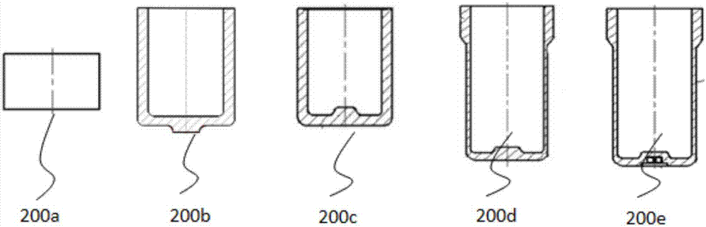
[0044] Please refer to image 3 , in a specific embodiment, the accumulator tank forging cold forging process provided by the present invention includes the following steps:

[0045] 1. Blanking: Take 20CrMnTi round steel and saw and cut it to form a rod-shaped blank 200a.

[0046] 2. The first spheroidizing annealing: use the annealing furnace to heat the rod-shaped billet 200a to a certain temperature for spheroidizing annealing, so as to reduce the hardness of the billet, achieve the purpose of softening the billet, and facilitate subsequent processes.

[0047] 3. Machining blanks: using a lathe to remove scale, micro-cracks and rust on the surface of the softened rod-shaped blank 200a to obtain a high-quality rod-shaped blank 2...


PUM


Abstract

The invention provides a cold-forging forming process for an energy accumulator tank forging. The cold-forging forming process comprises the steps of blanking, specifically, a rod-like blank is prepared; first reverse extrusion, specifically, the rod-like blank is placed into a first reverse extrusion die in a first predetermined shape to carry out first reverse extrusion to obtain a cup-shaped blank provided with a boss on the outer surface of the bottom; second extrusion, specifically, the cup-shaped blank is placed into a second reverse extrusion die with a second predetermined shape to carry out second reverse extrusion to obtain a cup-shaped blank provided with a boss on the inner surface of the bottom; third reverse extrusion, specifically, the cup-shaped blank is placed into a third reverse extrusion die with a third predetermined shape to carry out third reverse extrusion to obtain a cup-shaped blank provided with a step part; and fourth reverse extrusion, specifically, the cup-shaped blank is placed into a fourth reverse extrusion die with a fourth predetermined shape to carry out fourth reverse extrusion to obtain a finished product with an energy accumulator tank provided with a blind hole in the outer surface of the bottom. In the second reverse extrusion process of the cold-forging forming process for the energy accumulator tank forging, provided by the invention, the longitudinal pressure borne by the upper end surface of the cup-shaped blank is relatively small, so that the cup-shaped blank cannot be excessively upset, and the quality of the finished product of the energy accumulator tank forging is guaranteed.

Description

technical field [0001] The invention relates to the field of manufacturing energy accumulators for vehicles, in particular to a cold forging forming process and a back-extrusion die for an accumulator tank body forging. Background technique [0002] The accumulator is an energy storage device in the hydraulic pneumatic system, which can convert the excess pressure generated during the periodic operation of the hydraulic system into compression energy or potential energy and store it. When the system needs it, the compression or potential energy can be converted into Energy forms such as hydraulic pressure or air pressure are released to re-supply the system. Generally, the accumulator is composed of four parts: the tank body, the interlayer, the compressible gas on the interlayer, and the working liquid under the interlayer. The tank body is an important part of the accumulator, and it bears relatively high pressure in the working state. [0003] see figure 1 , which show...

Claims


Application Information

Patent Timeline
IPC IPC(8): B21C23/20B21C25/02
CPCB21C23/20B21C25/02
Inventor 聂相宜陈雪锋季微微袁永军任剑锋王成勇
Owner JIANGSU CHUANGYI PRECISION FORGING
Why Eureka
Try Eureka