Steel pipe concrete column and beam main bar connecting node and construction method thereof

A technology of steel tube concrete columns and connection nodes, which is applied in the direction of construction and building construction, to achieve the effects of guaranteed quality of finished products, low impact of shape changes, and reduced costs

Pending Publication Date: 2018-04-20
广西建工第五建筑工程集团有限公司
View PDF8 Cites 7 Cited by
  • Summary
  • Abstract
  • Description
  • Claims
  • Application Information

AI Technical Summary

Problems solved by technology

In order to overcome the existing technical problems in the construction and processing of beam-column joints in the combined structure of RC beams and circular steel pipe columns in the prior art

Method used


Image

  • Steel pipe concrete column and beam main bar connecting node and construction method thereof
  • Steel pipe concrete column and beam main bar connecting node and construction method thereof
  • Steel pipe concrete column and beam main bar connecting node and construction method thereof

Examples


Embodiment 1

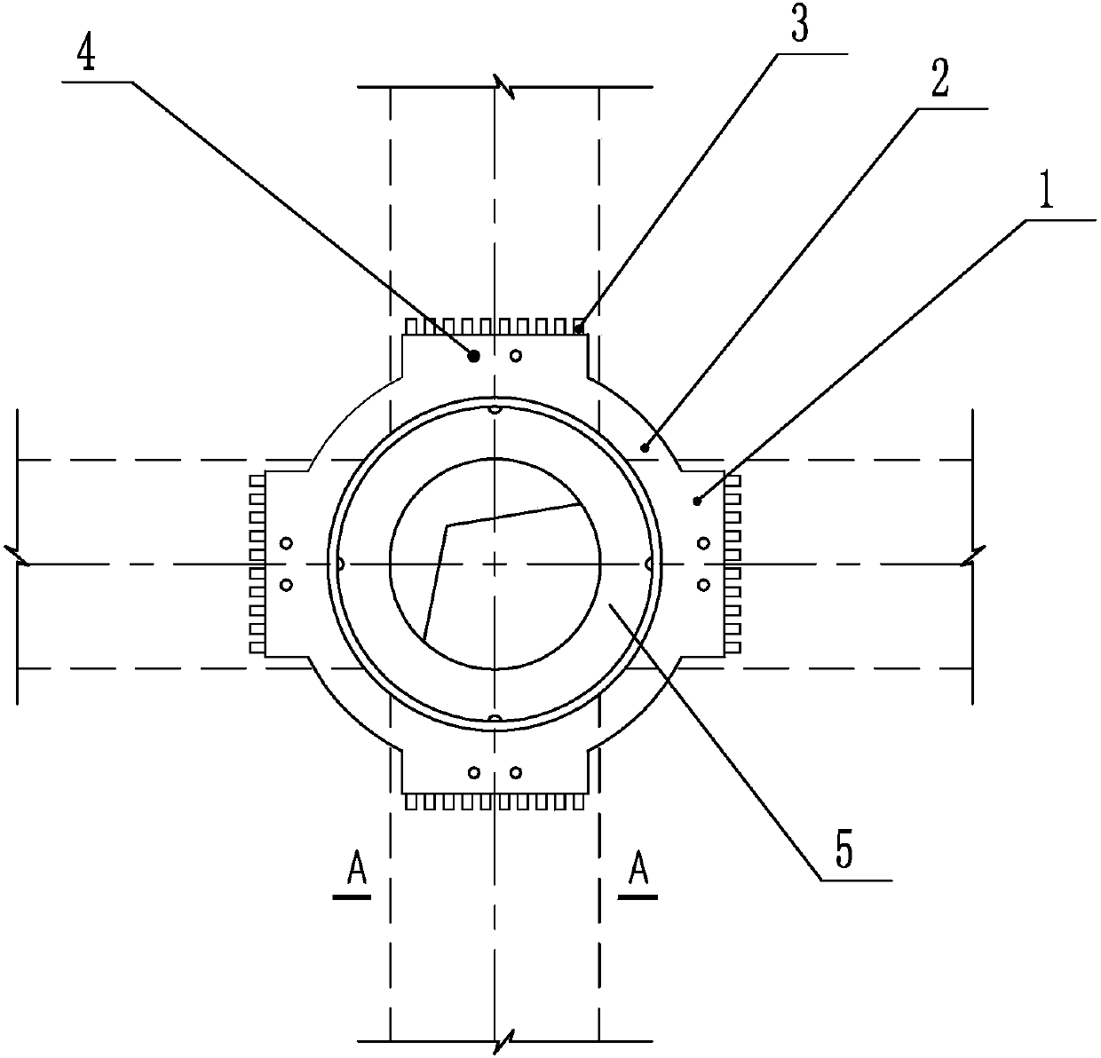
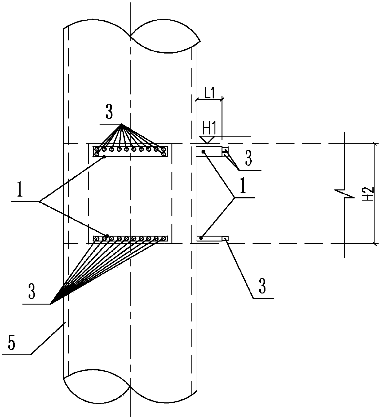
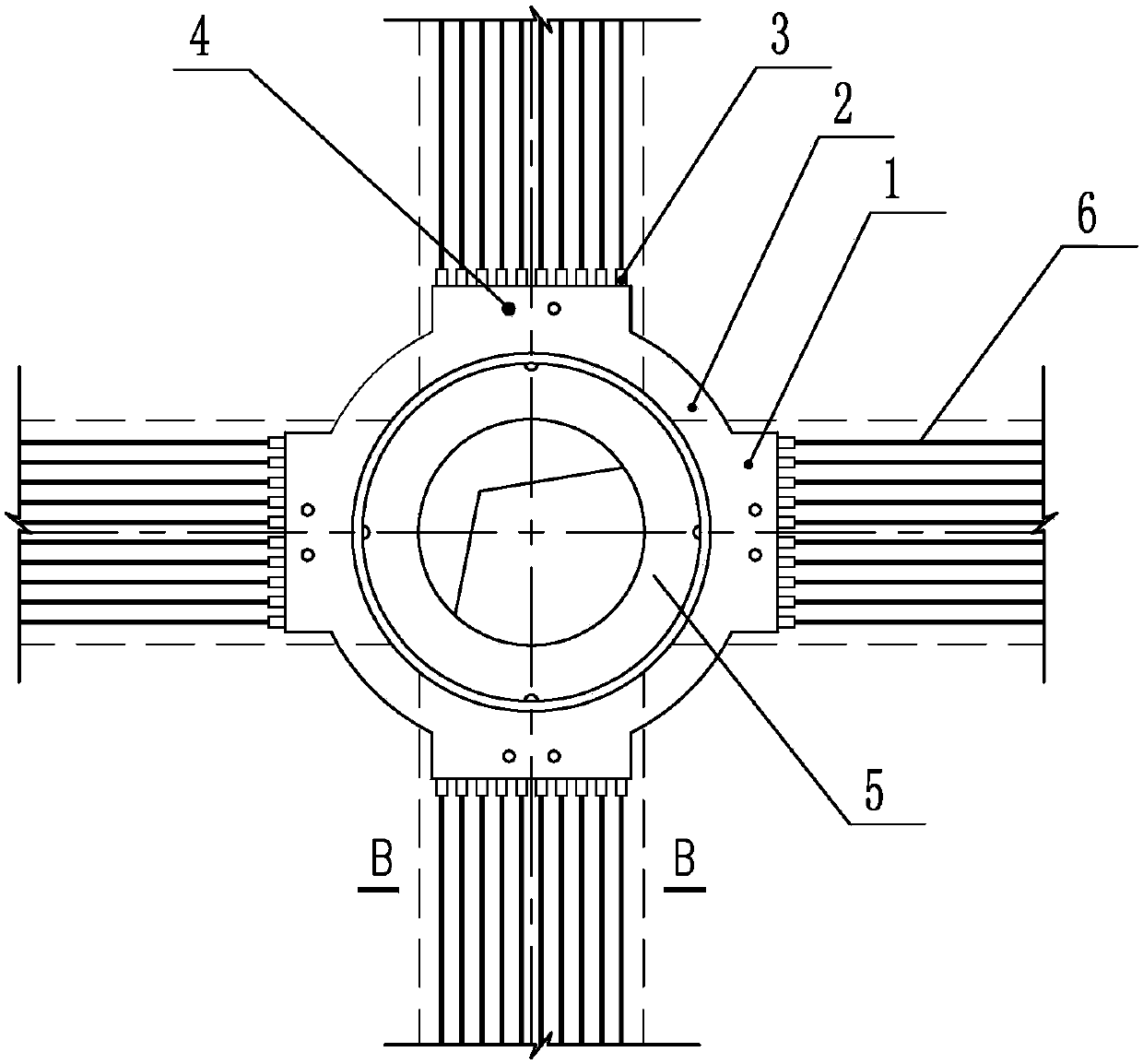
[0050] Such as figure 1 , figure 2 Shown: a connection node between a steel pipe concrete column and the main reinforcement of a beam, including a steel pipe column 5, a thick plate steel corbel 1 and a straight thread sleeve 3; the steel pipe column is also provided with a reinforcing ring plate 2; the reinforcing ring plate 2 and the thick plate steel corbel 1 are welded on the steel pipe column 5 as a whole. The upper surface of the reinforcing ring plate 2 is flush with the upper surface of the thick plate steel corbel 1 . One end of the thick-plate steel corbel 1 is welded to the steel pipe column 5, and the other end is welded to the end face of the straight thread sleeve 3. The thick-plate steel corbel 1 is also provided with two concrete air holes 4, and the concrete is air-permeable. The hole is a through hole penetrating through the steel corbel of the thick plate, which plays the role of ventilation when pouring concrete.

[0051] The length of the thick plate ...

Embodiment 2

[0055] A construction method for connecting a concrete-filled steel pipe column to a beam main reinforcement, the construction method is to utilize the connection node between a steel pipe concrete column and a beam main reinforcement connection node to carry out a method for connecting a concrete column to a beam main reinforcement, specifically comprising the following steps, refer to Figure 10 :

[0056] A. Steel structure detailed design (i.e. BIM modeling): According to the beam longitudinal reinforcement drawing, use Auto CAD, explorer TSSD, TeklaStructures and Revit software to combine 2D and 3D to set out and model the design drawings according to 1:1; Observe in detail the condition of the reinforcement of each beam-column node, pre-optimize the layout of the steel pipe column 5, thick steel plate corbel 1, straight thread sleeve 3 and beam reinforcement, and design the corresponding thick steel plate corbel according to the characteristics of the node beam reinforcem...


PUM

PropertyMeasurementUnit
lengthaaaaaaaaaa
diameteraaaaaaaaaa
distanceaaaaaaaaaa

Abstract

The invention relates to a steel pipe concrete column and beam main bar connecting node, which comprises a steel pipe column, thick plate steel corbels and straight threaded sleeves, wherein one end of each thick plate steel corbel is welded with the steel pipe column; the other end of each thick plate steel corbel is welded with the end surface of the corresponding straight threaded sleeve; and two concrete ventilated holes are also formed in each thick plate steel corbel. The connecting node provided by the invention effectively solves the difficult problems that beam bars, column bars, corbels, stiffening plates and the like in the node position are staggered and converged, and the construction space for node steel bar binding welding, concrete casting and the like is narrow, so that the steel bar anchoring quality and the concrete pouring compactness are difficult to control. Through the design of the thick plate steel corbels, the straight threaded sleeves are welded on the thickplate steel corbels; beam longitudinal bars are connected by using the straight threaded sleeves; and the phenomena of zero aperture ratio, zero node steel bar welding in a construction site and zeronode steel bar crossed penetration on the steel pipe column can be realized.

Description

technical field [0001] The invention relates to a connection node structure of a steel pipe concrete column and a beam main reinforcement, in particular to a connection node and a construction method of a steel pipe concrete column and a beam main reinforcement. Background technique [0002] At present, reinforced concrete beams (RC beams) in construction projects, that is, steel pipe concrete column composite structure beam-column joints, are mostly connected by reinforced rings: the longitudinal reinforcement in the beam is partly welded to the reinforced ring plate, and part of the holes are pierced through, such as Figure 11 shown. However, strengthening the ring joints brings a lot of inconvenience to the construction: [0003] 1. Due to the holes and reinforcements on the steel pipe column, the section of the steel pipe column at the node is weakened, which is unfavorable to the structure; [0004] 2. At the position where the multi-layer steel bars are overlapped an...

Claims


Application Information

Patent Timeline
Patent Type & Authority Applications(China)
IPC IPC(8): E04B1/18E04B1/58
CPCE04B1/185
Inventor 梁雄黄后玉彭媛吕锦昌罗祥军
Owner 广西建工第五建筑工程集团有限公司
Why Eureka
Try Eureka