Shadow mask assembly and reuse method of shadow mask assembly

A shadow mask and component technology, which is applied in the field of shadow mask components and shadow mask component reuse, can solve the problems of increasing production costs, reducing the yield of AMOLED glass substrates, and poor polishing effects, so as to reduce the number of polishing times and reduce production. Cost, the effect of improving flatness

Inactive Publication Date: 2017-06-23
WUHAN CHINA STAR OPTOELECTRONICS TECH CO LTD
View PDF8 Cites 6 Cited by
  • Summary
  • Abstract
  • Description
  • Claims
  • Application Information

AI Technical Summary

Problems solved by technology

[0004] The technical problem to be solved by the present invention is to provide a shadow mask assembly, which is used to solve the poor polishing effect in the prior art and the poor flatness of the surface where the solder joints are located, thereby affecting the flatness of the shadow mask diaphragm, resulting in the need for evaporation. The alignment between the plated AMOLED glass substrate and the shadow mask diaphragm is inaccurate, which reduces the yield of the AMOLED glass substrate and increases the production cost.

Method used


Image

  • Shadow mask assembly and reuse method of shadow mask assembly
  • Shadow mask assembly and reuse method of shadow mask assembly
  • Shadow mask assembly and reuse method of shadow mask assembly

Examples


Embodiment Construction

[0027] The following will clearly and completely describe the technical solutions in the embodiments of the present invention with reference to the accompanying drawings in the embodiments of the present invention. Obviously, the described embodiments are only some, not all, embodiments of the present invention. Based on the embodiments of the present invention, all other embodiments obtained by persons of ordinary skill in the art without making creative efforts belong to the protection scope of the present invention.

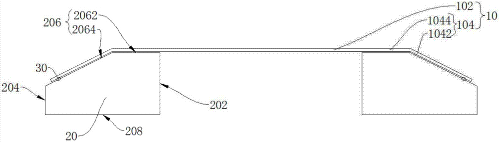
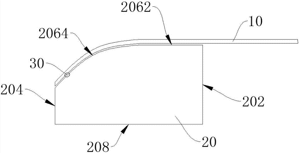
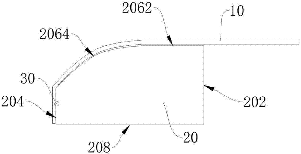
[0028] see figure 1 , figure 1 A schematic cross-sectional view of the shadow mask assembly provided by Embodiment 1 of the present invention is shown. As shown in the figure, the shadow mask assembly includes a shadow mask diaphragm 10 and a frame body 20, and the shadow mask diaphragm 10 is connected to the frame body 20 by welding the edge on the surface of the frame body 20, wherein the frame body 20 has a higher strength. Made of metal material, since t...


PUM


Abstract

The invention discloses a shadow mask assembly comprising a shadow mask membrane and frame bodies. Each frame body comprises an outer wall, an inner wall and a binding face connected with the outer wall and the inner wall, wherein the outer wall and the inner wall are arranged oppositely. The binding faces are bound with the shadow mask membrane. Each binding face comprises a welding area and a tiling area which are not coplanar. The welding areas are located between the tiling areas and the outer walls. The frame bodies fix the edge of the shadow mask membrane through welding spots arranged in the welding areas. The tiling areas are located between the welding areas and the inner walls and used for supporting the shadow mask membrane and keeping the shadow mask membrane being a plane. When the shadow mask membrane is replaced to be a new shadow mask membrane, the remaining welding spots of an original shadow mask membrane in the welding areas do not affect flatness of the shadow mask membrane, and therefore the yield rate of an AMOLED glass base plate used for vapor deposition is increased. After the shadow mask membrane is replaced for multiple times, one-time polishing and burnishing are conducted on all the welding spots in the welding areas, so that the burnishing times of the welding spots are decreased, and flatness of the shadow mask membrane is improved.

Description

technical field [0001] The invention relates to the field of display technology, in particular to a shadow mask assembly and a method for reusing the shadow mask assembly. Background technique [0002] The production of display panels of active matrix organic light emitting diodes or active matrix organic light emitting diodes (Active-matrix organiclight emitting diode, AMOLED) displays requires the use of fine metal masks (Fine Metal Mask) with very thin thickness and small thermal expansion coefficient. , FMM) as a shadow mask (or mask) to evaporate the organic luminescent body in the pixel of the display panel. Usually, the thickness of the shadow mask diaphragm is only 30-200 μm, which is thin and brittle. High position accuracy, the shadow mask diaphragm is usually laser welded on the metal frame to stretch the shadow mask diaphragm to form a shadow mask assembly. The area of ​​the shadow mask diaphragm is relatively large. Although the shadow mask diaphragm has been ...

Claims


Application Information

Patent Timeline
Patent Type & Authority Applications(China)
IPC IPC(8): C23C14/04C23C14/24
CPCC23C14/042C23C14/24H10K71/166C03C2218/151C03C17/002C03C2218/34H10K99/00
Inventor 曹绪文
Owner WUHAN CHINA STAR OPTOELECTRONICS TECH CO LTD
Why Eureka
Try Eureka