Supercharge Your Innovation With Domain-Expert AI Agents!

A drainage defoaming system and method for thermal nuclear power plants

A nuclear power plant and defoaming technology, which is applied in water conservancy projects, water conservancy engineering equipment, sea area engineering, etc., can solve the problems of serious foam problems, foam overflowing siphon wells, polluting plant areas, etc., and achieves strong adaptability, simple structure, and easy operation. The effect of low maintenance cost

Active Publication Date: 2019-04-02
CHINA INST OF WATER RESOURCES & HYDROPOWER RES
View PDF4 Cites 2 Cited by
  • Summary
  • Abstract
  • Description
  • Claims
  • Application Information

AI Technical Summary

Problems solved by technology

Early projects did not pay enough attention to the problem of drainage foam pollution, basically no anti-foaming and defoaming measures were taken for the drainage of power plants, and the foam problem was serious
In recent years, with the increasing environmental protection awareness of the whole people, the design of power plant drainage engineering has begun to consider anti-foaming and defoaming measures. It is difficult for engineering measures to meet the needs of tide level changes. Under low tide conditions, drainage is easy to be aerated to generate foam, and it is carried to the open sea, forming a foam pollution belt; second, existing engineering measures cannot completely prevent foam generation, and foam barriers are basically used. Measures to contain foam in the area behind the siphon well weir, the area behind the weir gradually accumulates foam, prone to foam overflowing the siphon well, polluting the factory area, etc. Further engineering measures are required to avoid foam accumulation and overflow

Method used


Image

  • A drainage defoaming system and method for thermal nuclear power plants
  • A drainage defoaming system and method for thermal nuclear power plants
  • A drainage defoaming system and method for thermal nuclear power plants

Examples


Embodiment 1

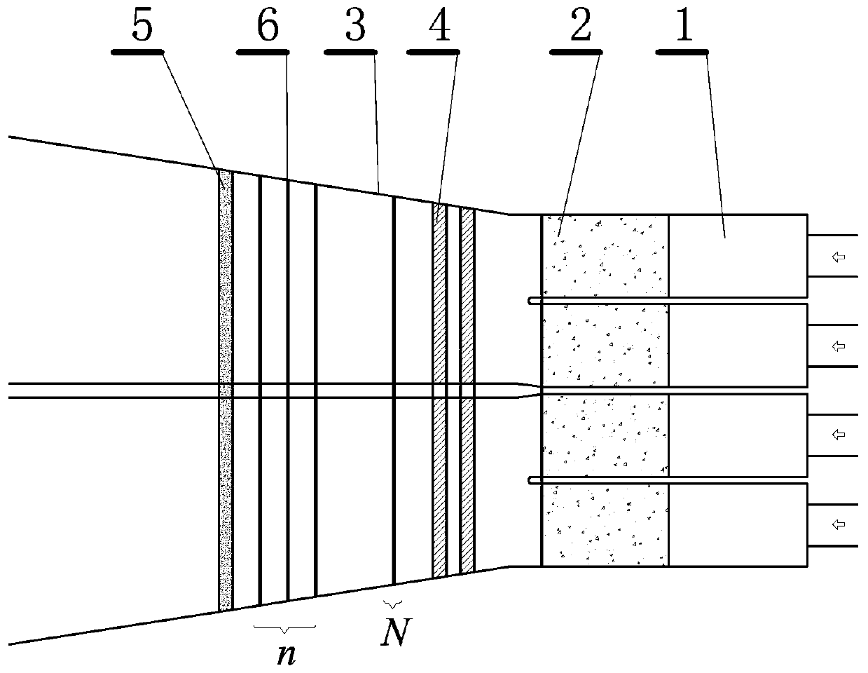
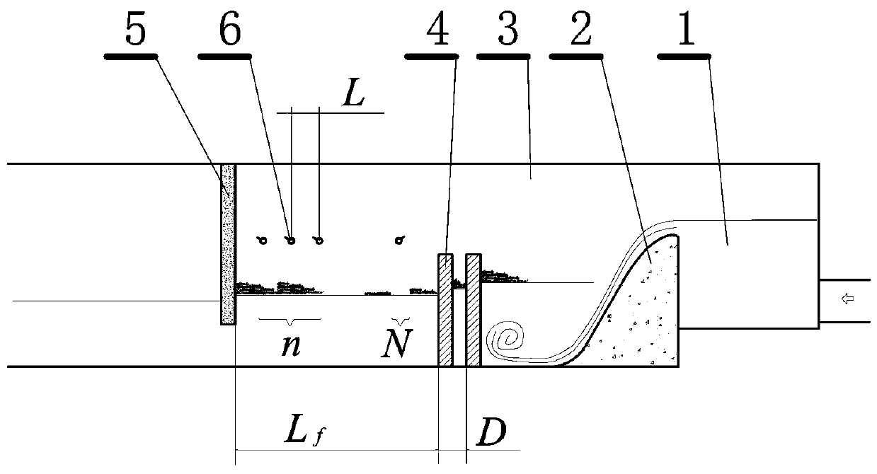
[0036] This embodiment is a kind of drainage defoaming system used in thermal / nuclear power plants, such as figure 1 , 2 shown. This embodiment includes: an overflow weir 2 arranged on the outlet side of the water inlet forebay 1 and a diffused rear pond channel 3, in which at least one energy-dissipating orifice plate 4 and a bubble-blocking wall are sequentially arranged 5. Sprinkling water facilities 6 are provided above the water area between the defoaming orifice plate and the foam blocking wall.

[0037] Before the system described in this embodiment was installed, after the drainage from the power plant fell from the overflow weir, a hydraulic jump was formed near the end of the overflow weir. was taken out to sea. In addition, affected by the hydraulic jump, the flow velocity distribution in the downstream cross-section of the siphon well is very uneven, and the water surface fluctuates greatly. The water level behind the weir is different, and the form of the hyd...

Embodiment 2

[0044] This embodiment is an improvement of the first embodiment, and is a refinement of the overflow weir in the first embodiment. The weir crest, the back water surface, and the floor of the pool channel in the diffusion section behind the weir of the overflow weir described in this embodiment are curved and sloped surfaces with smooth transitions.

[0045] In this example, the overflow weir with the smooth surface connecting the top of the weir and the water surface at the back of the weir is selected. Although it is a conventional overflow weir, it is very important for eliminating foam. This overflow weir can make the downstream water flow very stable, and cooperate with the downstream energy dissipation holes The high water level promoted by the board can minimize the generation of foam in the water and reduce the pressure of defoaming.

Embodiment 3

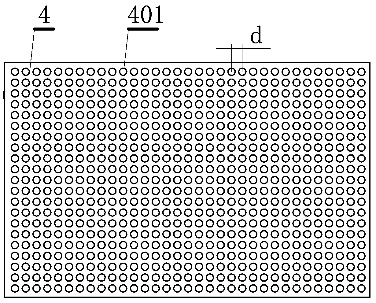
[0047] This embodiment is an improvement of the above-mentioned embodiment, and is a refinement of the above-mentioned embodiment about the energy-dissipating orifice. The energy dissipation orifice described in this embodiment is 2-4, and the distance D between each energy dissipation orifice is 800-1400 millimeters, see figure 2 , the holes on adjacent energy-dissipating orifice plates are arranged alternately.

[0048] Two energy-dissipating orifice plates are generally enough, but in some cases, if the drop of the overflow weir is large, so that the potential energy in the water is relatively large, more energy-dissipating orifice plates should be considered.

[0049] The distance between the orifice plates is related to the size of the foam in the water flow. The larger the foam is, the larger the distance between the orifice plates is. It can use energy dissipation and smooth water flow to intercept the foam.


PUM


Abstract

The invention relates to a water-draining defoaming system and method used for a fire nuclear power plant. The water-draining defoaming system comprises an overflow weir arranged at a water outlet side of a water inlet front tank and a divergent weir rear pool channel, wherein at least one orifice plate for dissipating energy and a foam blocking wall are sequentially arranged in the weir rear pool channel; and a spraying water facility is arranged above a water area between the orifice plate for dissipating energy and the foam blocking wall. According to the water-draining defoaming system, the orifice plate for dissipating energy, the foam blocking wall, the spraying water facility and the like are arranged outside a water-draining siphon well of the fire nuclear power plant, so that foams generated by the siphon well are completely processed before being discharged, and therefore, a contamination phenomenon that vast stretches of foams appear in a water-draining area is avoided. On the premise of not increasing earth excavation amount, a facility of eliminating foams is directly arranged in the original water-draining divergent pool channel, so that a defoaming function is realized. The water-draining defoaming system has the characteristics of being strong in adaptation, high in efficiency and green and pollution-free, is simple in structure, and is relatively low in operation and maintenance cost.

Description

technical field [0001] The invention relates to a drainage defoaming system and method for thermal nuclear power plants, a hydraulic facility and a design method, and an environmental protection system and method for reducing drainage foam pollution. Background technique [0002] The environmental impact of thermal / nuclear power plant drainage foam is ubiquitous. Early projects did not pay enough attention to the problem of foam pollution in drainage. Basically, no anti-foaming and defoaming measures were taken in the drainage of power plants, and the foam problem was serious. In recent years, with the increasing environmental protection awareness of the whole people, the design of power plant drainage engineering has begun to consider anti-foaming and defoaming measures. It is difficult for engineering measures to meet the needs of tide level changes. Under low tide conditions, drainage is easy to be aerated to generate foam, and it is carried to the open sea, forming a fo...

Claims


Application Information

Patent Timeline
Patent Type & Authority Patents(China)
IPC IPC(8): E02B1/00E02B8/06
CPCE02B1/003E02B8/06
Inventor 纪平秦晓陈文焕赵懿珺陈小莉张强梁洪华曾利张海文袁珏康占山
Owner CHINA INST OF WATER RESOURCES & HYDROPOWER RES
Features
  • R&D
  • Intellectual Property
  • Life Sciences
  • Materials
  • Tech Scout
  • Unparalleled Data Quality
  • Higher Quality Content
  • 60% Fewer Hallucinations
Learn More