Novel phase change energy storage type device and method

A technology of phase change heat storage and phase change heat storage materials, which is applied in the field of new phase change heat storage devices, can solve the problems of difficult device assembly and maintenance, restrictions on large-scale commercial applications, and short cycle life, achieving simple structure, The effect of low density and low device cost

Pending Publication Date: 2017-06-23
PIONEER ENERGY JIANGSU
View PDF7 Cites 10 Cited by
  • Summary
  • Abstract
  • Description
  • Claims
  • Application Information

AI Technical Summary

Problems solved by technology

However, inorganic hydrated salt phase change materials have disadvantages such as large subcooling, phase separation, and short cycle life, which limit their large-scale commercial application; at the same time, all heat exchange components or pipes inside the heat storage device of traditional phase change heat storage materials, Complex structure, high cost, difficult device assembly and maintenance

Method used


Image

  • Novel phase change energy storage type device and method
  • Novel phase change energy storage type device and method

Examples


Embodiment 1

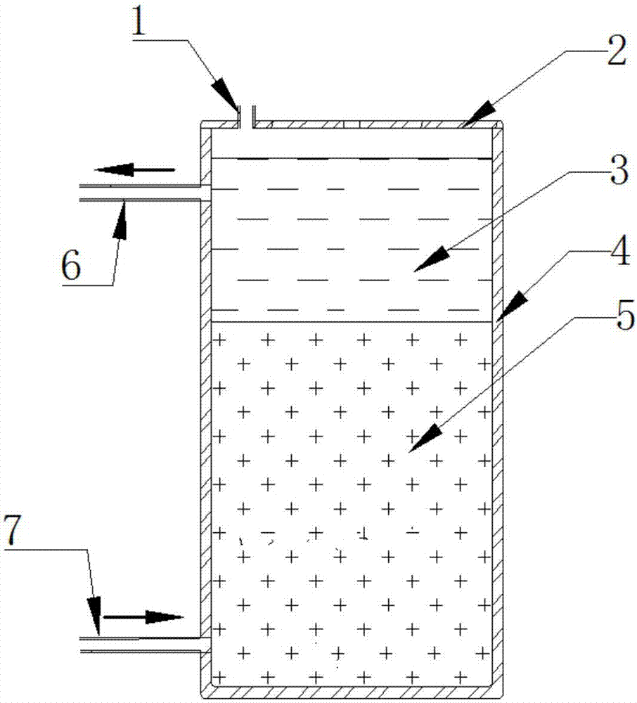
[0030] Such as figure 1 As shown, a new phase change heat storage device includes a storage container 2, an insulation layer 4 arranged outside the storage container 2, a ventilation pipe 1, a phase change heat storage material 5 and a heat exchange medium 3; the storage container 2. The side wall is also provided with an inlet pipe 7 and an outlet pipe 6. The density of the heat exchange medium 3 is lower than that of the phase-change heat storage material 5, so that the phase-change heat storage material 5 is in the lower part of the storage container 2 in both solid and liquid states. When the device is charging and discharging heat, the heat exchange medium 3 circulates and flushes the phase change heat storage material 5 to realize convective heat exchange between the two.

[0031] When in use, the heat exchange medium 3 enters the material storage container 2 from the inlet pipe 7 , directly contacts with the phase change heat storage material for heat exchange and moves...

Embodiment 2

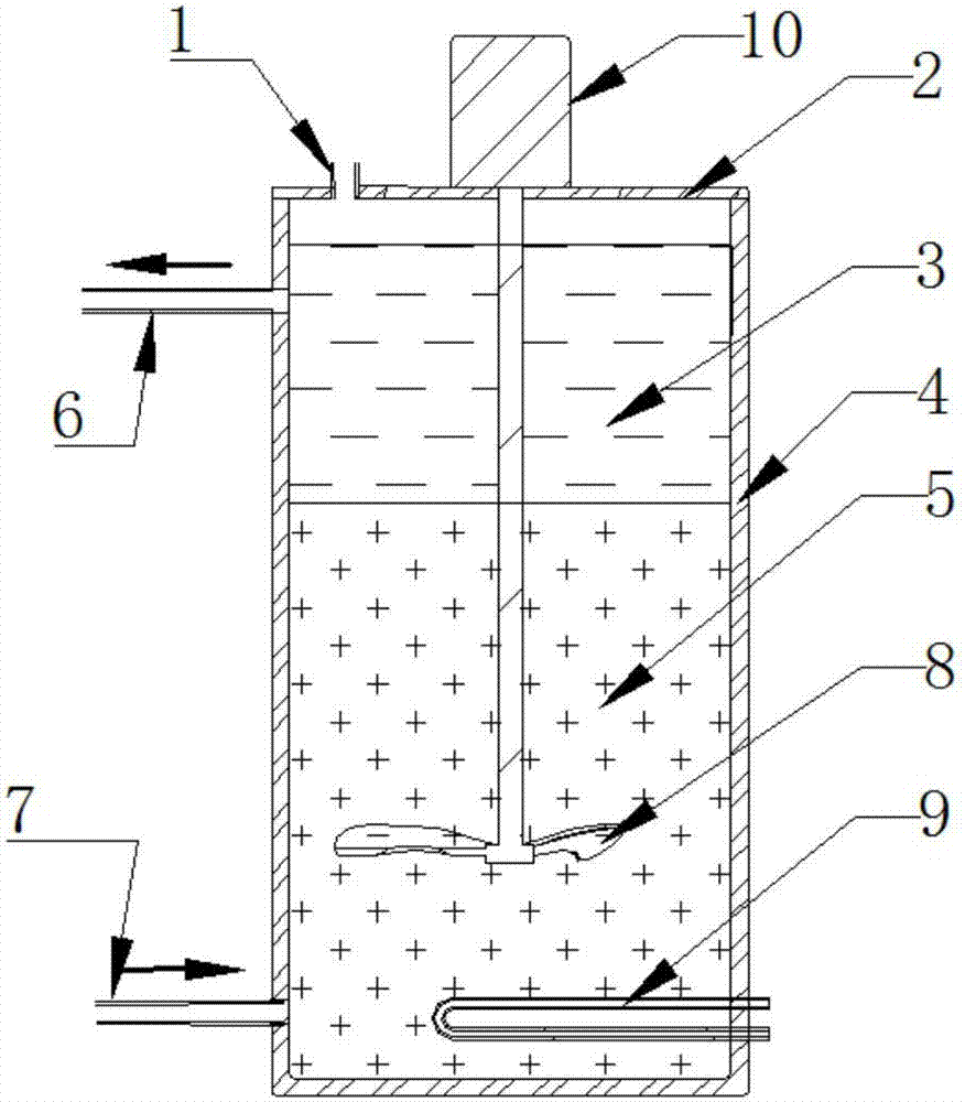
[0033] Such as figure 2 As shown, the heat of the heat source in this embodiment can come from the electric heater 9 built in the storage container 2, and the relative flow between the heat exchange medium 3 and the phase change material 5 driven by the agitation of the stirrer 10 can realize the interaction between the two. For convective heat exchange, a stirrer 10 is installed on the material storage container 2, and the stirrer 10 is equipped with a stirring paddle 8 to enhance the heat exchange effect. All the other are with embodiment 1.


PUM


Abstract

The invention relates to a novel phase change energy storage type device. The device comprises a storage container (2), a phase change heat storage material (5) and a heat exchange medium (3) are arranged in the heat storage container (2), an inlet pipeline (7) and an outlet pipeline (6) allowing the heat exchange medium (3) to circulate are arranged on the side wall of the storage container (2), the phase change heat storage material (5) and the heat exchange medium (3) make direct contact and are not soluble, the density of the heat exchange medium (3) is smaller than that of the phase change heat storage material (5), the inlet pipeline (7) is located on the lower portion of the storage container (2), and the outlet pipeline (6) is located on the upper portion of the storage container (2). Compared with the prior art, the device is simple in structure, no heat exchange pipeline assemblies exist in the interior, the heat exchange efficiency is high, maintenance is convenient, the cost is low, meanwhile, the off-peak electricity can be used for heat storage, the running cost is low, and the device is suitable for large-scale batched production.

Description

technical field [0001] The invention relates to the technical field of phase change material energy storage, in particular to a novel phase change heat storage device and method. Background technique [0002] With the growth of the national economy, the rapid development of science and technology, and the strengthening of people's awareness of green environmental protection, the form of coal boiler heating is increasingly replaced by heating equipment related to phase change heat storage materials, of which phase change heat storage materials have heat storage density Large, small size, high heat transfer efficiency and other advantages. [0003] Phase change heat storage technology uses the latent heat of phase change materials to realize the storage and utilization of thermal energy, and is an effective way to alleviate the mismatch between energy supply and demand in terms of time, intensity and space. Solid-liquid phase change materials have attracted extensive attentio...

Claims


Application Information

Patent Timeline
Patent Type & Authority Applications(China)
IPC IPC(8): F28D20/02F28F13/12
CPCF28D20/021F28F13/125Y02E60/14
Inventor 王鈜李明涛刘海军童榆翔
Owner PIONEER ENERGY JIANGSU
Why Eureka
Try Eureka