Oil Cooled Battery Pack

A battery pack, oil cooling technology, applied in secondary batteries, battery pack components, battery caps/end caps, etc., can solve problems such as affecting the service life of the battery pack, difficult to balance the internal flow field, and difficult to lower the battery pack. , to achieve the effect of increasing the heat dissipation effect, simple structure and low cost

Active Publication Date: 2020-01-03
先进储能材料国家工程研究中心有限责任公司
View PDF8 Cites 0 Cited by
  • Summary
  • Abstract
  • Description
  • Claims
  • Application Information

AI Technical Summary

Problems solved by technology

[0002] As the use of battery packs becomes more and more widespread, the existing air-cooled battery packs have long air-cooled flow channels and difficult to balance the internal flow field, resulting in differences in cooling effects in different areas, large temperature differences in batteries, inability to waterproof and dustproof, and volume Large (as long as the volume occupied by the fan and air duct), high cost, etc., can no longer fully meet the market requirements
For some airtight conditions, such as cruise ships, yachts, and cars, due to poor ventilation, if air cooling is used to dissipate heat, it is difficult to lower the temperature of the battery pack, which will affect the service life of the battery pack and cause use costs. higher

Method used


Image

  • Oil Cooled Battery Pack
  • Oil Cooled Battery Pack
  • Oil Cooled Battery Pack

Examples


Embodiment 1

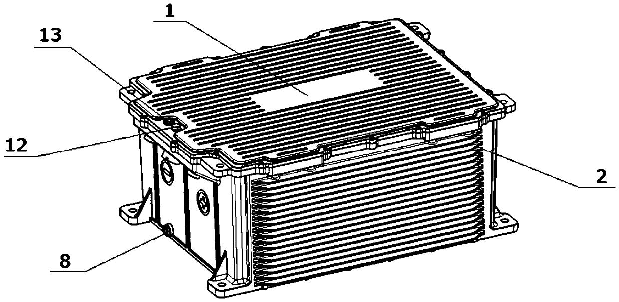
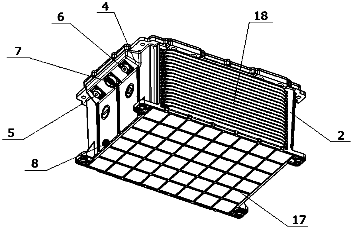
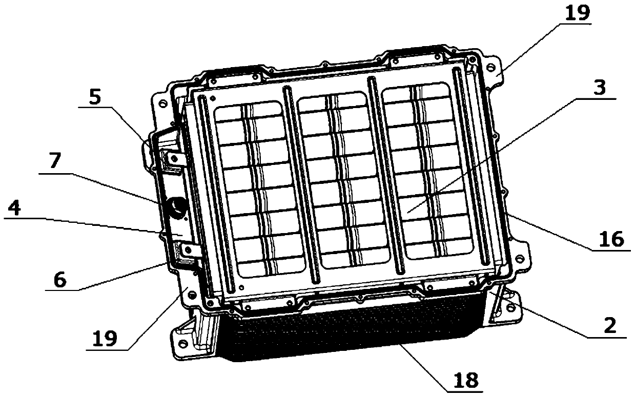
[0025] An oil-cooled battery pack, such as figure 1 , figure 2 As shown, including the upper cover 1, the box body 2 and the battery pack module 3, such as Figure 5 As shown, the upper end of one end surface of the box body 2 is provided with an outwardly protruding functional interface cavity 4, the bottom of the functional interface cavity 4 is inclined upward with the outer end facing upward, and the angle formed between the bottom of the functional interface cavity and the horizontal plane is The positive output terminal 5, the negative output terminal 6 and the communication connection terminal 7 are arranged at the bottom of the functional interface cavity 4, and the function connection between the positive output terminal 5, the negative output terminal 6 and the communication connection terminal 7 and the box body 2 An insulating sleeve is set between the cavity 4 (the insulating sleeve is not shown in the figure), and epoxy resin glue is used to glue and connect th...

Embodiment 2

[0027] An oil-cooled battery pack, the structure of which is similar to the oil-cooled battery pack in Example 1, the difference is that: the angle formed between the bottom of the functional interface cavity and the horizontal plane is 20 degrees, and the The number of communication connection terminals is two.

Embodiment 3

[0029] An oil-cooled battery pack, the structure of which is similar to the oil-cooled battery pack in Embodiment 1, the difference is that the angle formed between the bottom of the functional interface cavity and the horizontal plane is 40 degrees.


PUM


Abstract

The invention provides an oil-cooled battery pack, which includes an upper cover, a box body and a battery pack module. An outwardly protruding functional interface cavity is provided on the upper end of one end surface of the box body, and the bottom of the functional interface cavity faces upwards. Inclined upward at a certain angle, the bottom of the functional interface cavity is provided with a positive output terminal, a negative output terminal and at least one communication connection terminal, heat sinks are provided on both sides of the box, and at least one oil outlet is provided on the end surface of the box near the bottom ;The inner side of the upper cover is provided with heat conduction fins, the outer side of the upper cover is provided with heat dissipation ribs, and the upper cover is provided with at least one water blocking exhaust valve and at least one oil filling port; the battery pack module is placed in the box, and the box is equipped with oily Liquid, oily liquid completely submerges the battery pack module and the oily liquid is in contact with the heat conduction sheet inside the upper cover, and the upper cover and the box body are matched and sealed together. The oil-cooled battery pack of the present invention has simple structure, novel arrangement, convenient installation and good heat dissipation effect.

Description

technical field [0001] The invention relates to a battery pack, in particular to an oil-cooled battery pack. Background technique [0002] As the use of battery packs becomes more and more widespread, the existing air-cooled battery packs have long air-cooled flow channels and difficult to balance the internal flow field, resulting in differences in cooling effects in different areas, large temperature differences in batteries, inability to waterproof and dustproof, and volume Large (as long as the volume occupied by the fan and air duct), high cost and other issues can no longer fully meet the market requirements. For some airtight conditions, such as cruise ships, yachts, and cars, due to poor ventilation, if air cooling is used to dissipate heat, it is difficult to lower the temperature of the battery pack, which will affect the service life of the battery pack and cause use costs. higher. Aiming at the deficiency of the above-mentioned air-cooled battery pack, battery ...

Claims


Application Information

Patent Timeline
Patent Type & Authority Patents(China)
IPC IPC(8): H01M2/02H01M2/04H01M2/06H01M2/08H01M2/12H01M10/613H01M10/6555H01M10/6551H01M10/6567H01M50/102H01M50/148H01M50/166H01M50/183H01M50/392
CPCH01M10/613H01M10/6551H01M10/6555H01M10/6567H01M50/10H01M50/147H01M50/183H01M50/172H01M50/30Y02E60/10
Inventor 钟发平陈勇军郭军团廖泽源徐国昌匡德志
Owner 先进储能材料国家工程研究中心有限责任公司
Why Eureka
Try Eureka