Electromagnetic induction transparent effect-based all-dielectric polarization converter

A technology of electromagnetic induction transparency and polarization conversion, which is applied in the direction of circuits, electrical components, waveguide devices, etc., can solve the problems of limiting the application of polarized devices, the thickness of polarized devices is unfavorable, and the loss of integrated polarized devices in photonic systems. Achieve the effects of low polarization conversion, low loss, and thin thickness

Inactive Publication Date: 2017-06-23
QIQIHAR UNIVERSITY
View PDF2 Cites 5 Cited by
  • Summary
  • Abstract
  • Description
  • Claims
  • Application Information

AI Technical Summary

Problems solved by technology

[0004] The present invention aims to solve the problem that the large thickness of the existing polarized device is not conducive to the integration of photonic systems or the high loss of the polarized device made of metal materials, which limits the application of the polarized device, and proposes an all-dielectric based on the electromagnetic induction transparency effect Polarization converter

Method used


Image

  • Electromagnetic induction transparent effect-based all-dielectric polarization converter
  • Electromagnetic induction transparent effect-based all-dielectric polarization converter
  • Electromagnetic induction transparent effect-based all-dielectric polarization converter

Examples


specific Embodiment approach 1

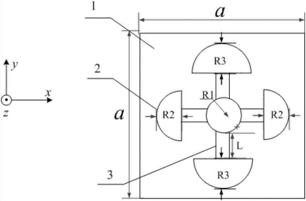
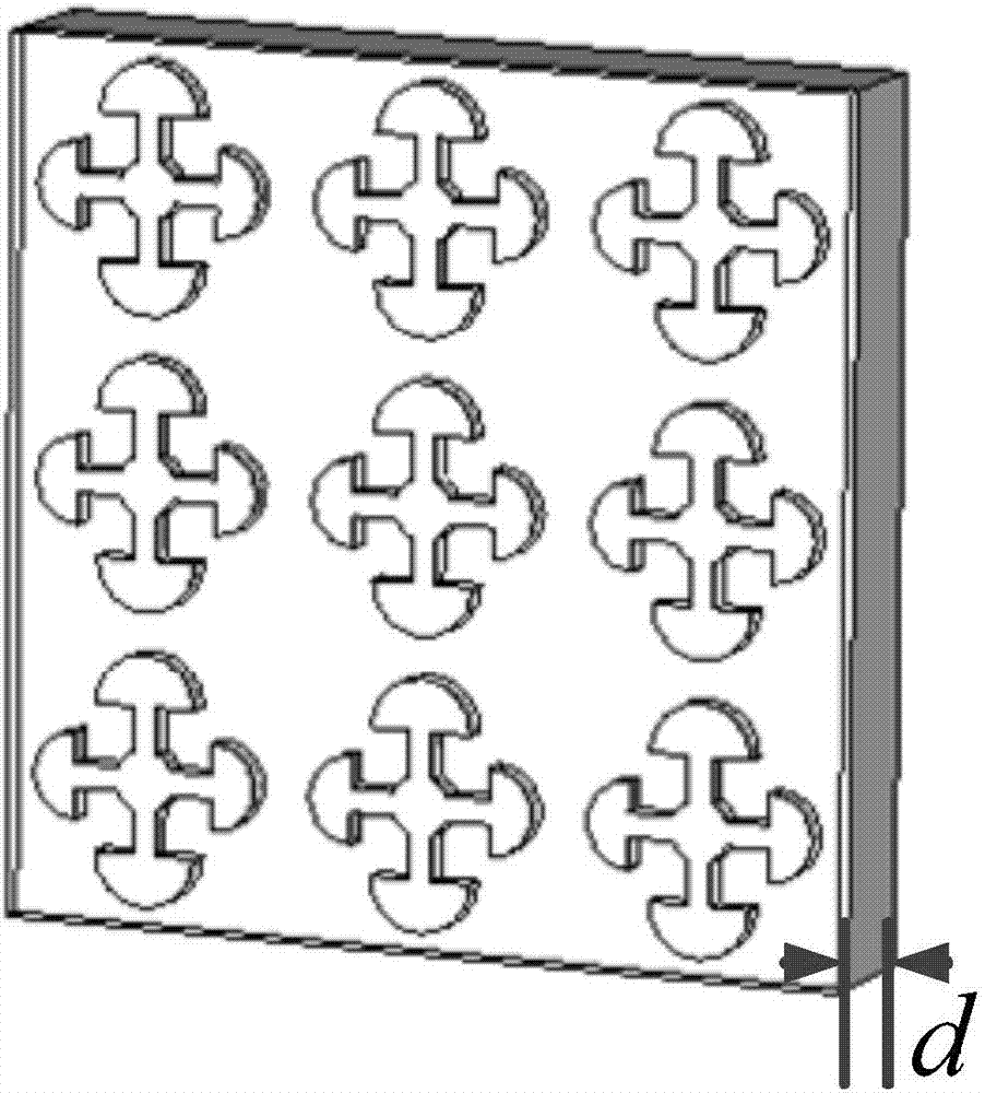
[0027] Specific implementation mode 1. Combination figure 1 with figure 2 Describe this embodiment mode, an all-dielectric polarization converter based on the electromagnetic induction transparency effect described in this embodiment mode, which includes n dielectric surface units, and each dielectric surface unit includes a square substrate 1, four semicircular Dielectric brick 2 and four dielectric wires 3; n is a positive integer.

[0028] Four semi-circular dielectric bricks 2 are set opposite to each other, and the radius of the two semi-circular dielectric bricks 2 oppositely arranged is the same, and one end of the four dielectric lines 3 is respectively connected to the rectangular sides of the four semi-circular dielectric bricks 2 , the other ends of the four dielectric wires 3 are fixedly connected to form a "ten" shape, and the four semicircular dielectric bricks 2 and the four dielectric wires 3 are all arranged on the upper surface of the square substrate 1 . ...

specific Embodiment approach 2

[0030] Specific embodiment 2. This embodiment is a further description of a kind of all-dielectric polarization converter based on electromagnetic induction transparency effect described in specific embodiment 1 or 2. Four dielectric wires 3 are fixedly connected to form a "cross" shape The point of intersection is a circle.

specific Embodiment approach 3

[0031] Specific Embodiment 3. This embodiment is a further description of the all-dielectric polarization converter based on the electromagnetic induction transparency effect described in the specific embodiment 1 or 2. Four dielectric wires 3 are fixedly connected to form a "cross" shape The radius of the intersection circle is R 1 ; 1 = 25 μm.


PUM


Abstract

The invention provides an electromagnetic induction transparent effect-based all-dielectric polarization converter, and relates to a low-loss and ultra-thin all-dielectric polarization converter, which solves the problem that the application of a polarization device is limited as a result of the unfavorable integration of a photon system or the high loss of the polarization device made of metal materials caused by the thickness factor of an existing polarization device in the prior art. The all-dielectric polarization converter comprises four semicircular medium bricks, wherein the four semicircular medium bricks are oppositely arranged two by two. Every two oppositely arranged semicircular medium bricks are the same in radius. One ends of four medium lines are respectively connected with the rectangular side surfaces of the four semicircular medium bricks. The other ends of four medium lines are fixedly connected to be in the + shape. The four semicircular medium bricks and the four medium lines are arranged on the upper surface of a square substrate. The above device can be used as an all-dielectric polarization converter.

Description

technical field [0001] The invention relates to a low-loss, ultra-thin all-dielectric polarization converter. Background technique [0002] At present, polarization problems are involved in many fields such as anomalous refraction, holograms, and quarter-wave plates. Therefore, controlling the polarization state of electromagnetic waves has attracted widespread attention from scientists. In order to control the polarization state of electromagnetic waves, scholars have proposed many effective methods, which can be done by controlling the amplitude and phase of electromagnetic waves in the absorption spectrum, transmission spectrum, and reflection spectrum. However, the thickness of traditional polarized devices is very large, which is comparable to the wavelength, which is very inconvenient for it to be integrated into existing photonic systems. [0003] Recent studies have shown that metamedia can be used to control the polarization state of electromagnetic waves. In part...

Claims


Application Information

Patent Timeline
Patent Type & Authority Applications(China)
IPC IPC(8): H01P1/17
CPCH01P1/172
Inventor 朱磊董亮题原付壮壮李泰成李健李渊雷煜鑫
Owner QIQIHAR UNIVERSITY
Why Eureka
Try Eureka