Plasma gas treatment device

A plasma and gas treatment technology, which is applied in the direction of gas treatment, separation methods, and dispersed particle separation, etc., can solve the problems of unsatisfactory gas treatment effects, achieve high working intensity, uniform contact, and avoid gas short circuit effects

Inactive Publication Date: 2017-06-27
苏州盟力环境科技有限公司
View PDF9 Cites 4 Cited by
  • Summary
  • Abstract
  • Description
  • Claims
  • Application Information

AI Technical Summary

Problems solved by technology

[0004] The low-temperature plasma waste gas treatment equipment in the prior art generally adopts a parallel-surface thorn-plate discharge structure. This static discharge structure has little disturbance to the gas, and the gas treatment effect is not ideal.

Method used


Image

  • Plasma gas treatment device
  • Plasma gas treatment device

Examples


Embodiment

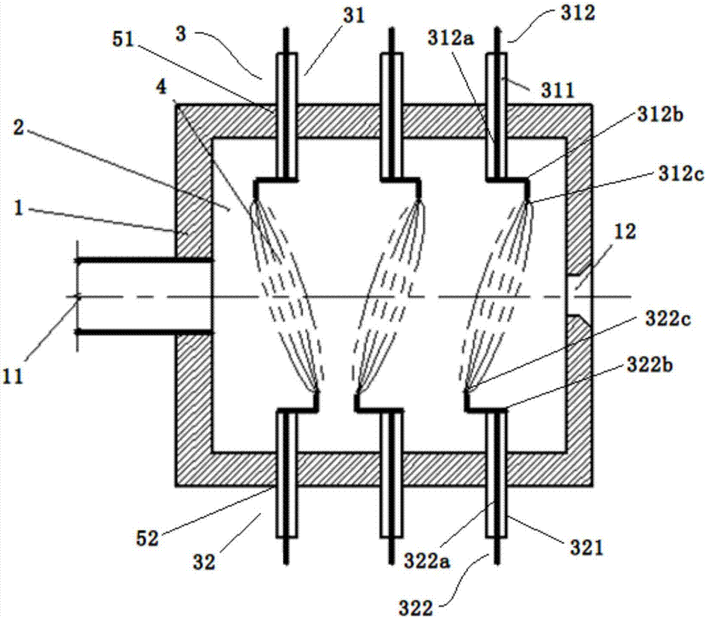
[0033] This embodiment provides a plasma gas processing device, which enhances the gas disturbance in the reaction chamber, not only has a good gas processing effect, but also has a simple structure and low manufacturing cost.

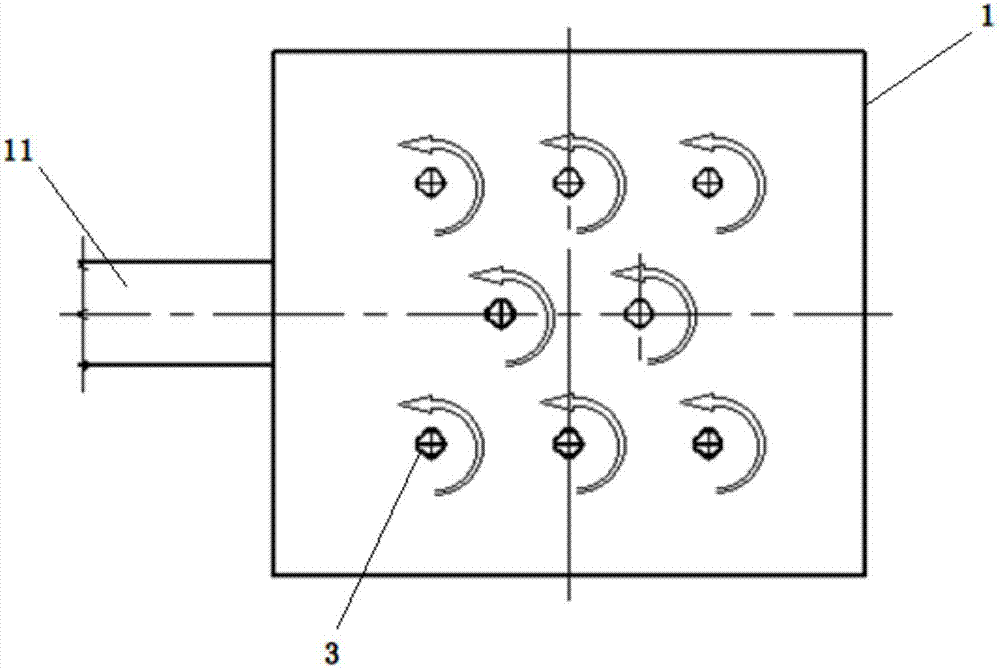
[0034] See figure 1 with figure 2 ,among them figure 1 Is a schematic structural diagram of a plasma gas processing device according to an embodiment of the present invention; figure 2 Shown is a top view of a plasma gas processing apparatus according to an embodiment of the present invention.

[0035] It can be seen from the figure that the plasma gas processing device of this embodiment includes a housing 1 which defines a reaction chamber 2; an air inlet 11 and an air outlet 12 are respectively provided at the front and rear of the housing 1. The gas inlet 11 and the gas outlet 12 are used to guide gas into and out of the reaction chamber 2; a plurality of plasma generating units 3 arranged in an array, The plasma generating units 3 of adjacent array...


PUM


Abstract

The invention relates to a plasma gas treatment device which comprises a shell, a gas inlet, a gas outlet, multiple arrayed plasma generation units and a control unit, wherein a reaction cavity is defined in the shell; the gas inlet and the gas outlet are respectively formed in two ends of the shell and communicate with the reaction cavity; every two adjacent arrayed plasma generation units are crossed; and the control unit is connected with the plasma generation units. Each plasma generation unit comprises a positive electrode part and a negative electrode part which are oppositely arranged in a spacing manner; each positive electrode part comprises a first discharge body located in the reaction cavity; each negative electrode part comprises a second discharge body located in the reaction cavity; the first discharge bodies and the second discharge bodies are arranged in a staggering manner; and the control unit is used for controlling the first discharge bodies and the second discharge bodies to rotate relative to the shell. The gas treatment device disclosed by the invention enhances disturbance of gas in the reaction cavity, has an extremely good gas treatment effect, and is simple in structure and low in manufacturing cost.

Description

Technical field [0001] The present invention relates to the technical field of gas processing, in particular to a plasma gas processing device. Background technique [0002] In recent years, with the development of the economy, a large number of new chemical enterprises have started, and the environmental protection investment of enterprises is insufficient, which has led to the emission of a large amount of industrial organic waste gas, which has caused a decline in the quality of the atmospheric environment and brought serious harm to human health. Treatment of organic waste gas. At present, the treatment of organic waste gas generally adopts organic waste gas activated carbon adsorption treatment method, catalytic combustion method, catalytic oxidation method, acid-base neutralization method, etc. However, the above-mentioned waste gas treatment method still has conversion for the treatment of low concentration and large flow organic waste gas. The problem of low efficiency a...

Claims


Application Information

Patent Timeline
Patent Type & Authority Applications(China)
IPC IPC(8): B01D53/74B01D53/44
CPCB01D53/44B01D53/74B01D2259/818
Inventor 刘忻李祥
Owner 苏州盟力环境科技有限公司
Why Eureka
Try Eureka