Automatic production device for stator piece and rotor piece

A technology for producing devices and stators and rotors, which is applied to positioning devices, manufacturing stator/rotor bodies, feeding devices, etc., can solve problems such as the inability of mass production to meet the requirements, the large difference between the stator and rotor pieces and the standard pieces, and the consumption of human resources. Achieve the effect of satisfying large-scale continuous production, realizing automatic operation and reducing costs

Active Publication Date: 2017-06-27
苏州市华能发电机有限公司
View PDF6 Cites 12 Cited by
  • Summary
  • Abstract
  • Description
  • Claims
  • Application Information

AI Technical Summary

Problems solved by technology

The above-mentioned traditional method relies on manual feeding and retrieving of the stator and rotor blades, which is labor-intensive and consumes human resources, and workers are prone to fatigue after working for a long time, leading to safety accidents such as work-related injuries; errors are likely to occur during manual feeding, which leads to Stamping and forming stator and r

Method used


Image

  • Automatic production device for stator piece and rotor piece
  • Automatic production device for stator piece and rotor piece
  • Automatic production device for stator piece and rotor piece

Examples


Example Embodiment

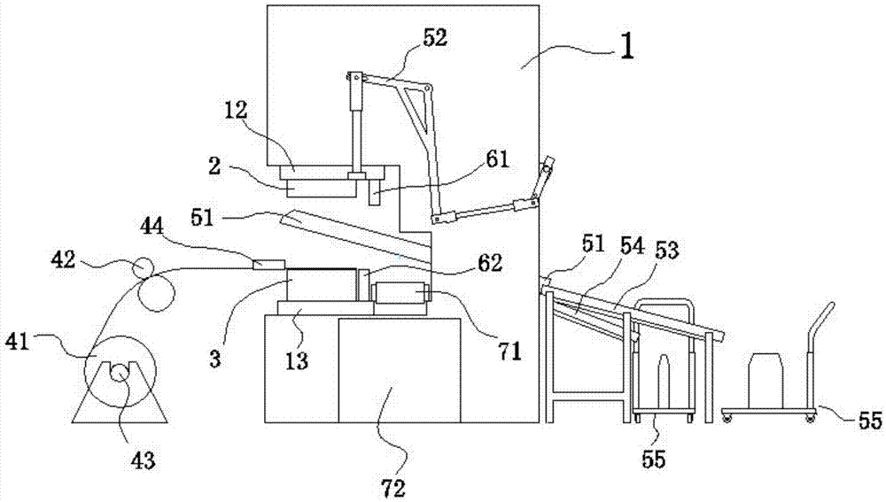
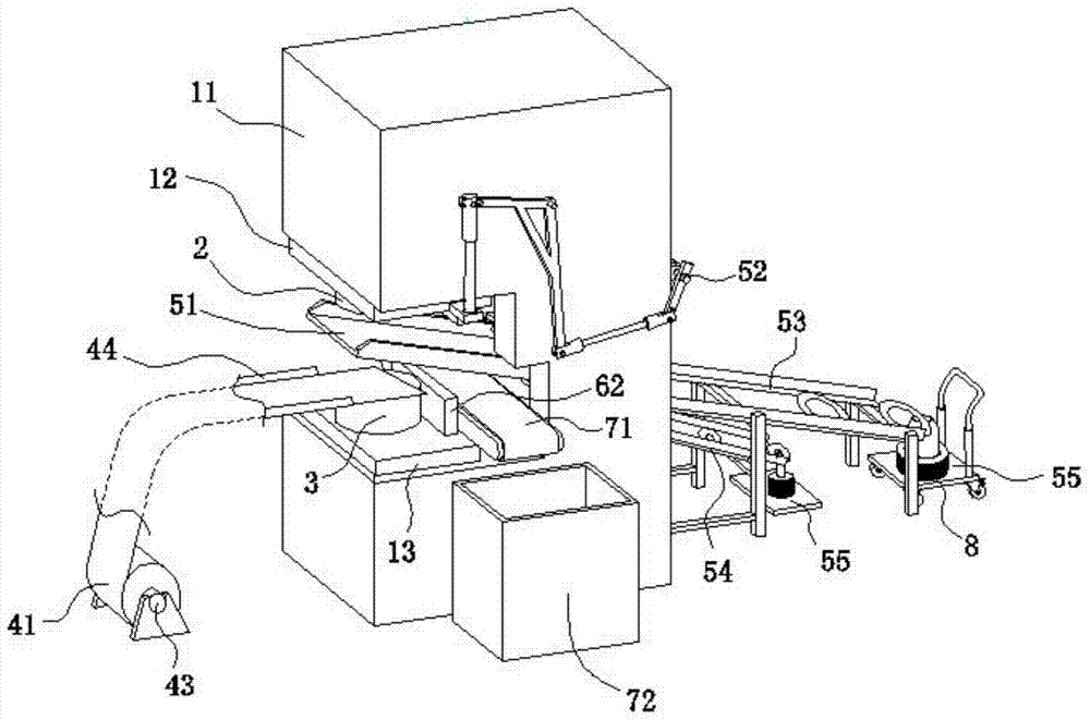
[0021] Such as Figure 1 to Figure 2 As shown, an automatic production device for stator and rotor blades includes a punch 1, a control system, an upper mold 2, a lower mold 3, a suction device, a feeding device, a finished product receiving device 5, a scrap cutter, and a scrap receiving device. The punch 1 is provided with a bed frame 11, an upper mold base 12, a lower mold base 13, and a driving unit for driving the upper mold base 12 to move downward. The upper mold base 12, the lower mold base 13 and the driving unit are located at the front end of the bed frame 11. The upper mold 2 and the lower mold 3 are fixedly mounted on the upper mold base 12 and the lower mold base 13, respectively, the upper mold 2 is provided with suction holes, and the suction device is connected with the upper mold 2 through the suction holes. The feeding device is located in front of the punch 1. The feeding device is provided with a roll 41, a reel 43 and a roll feeding mechanism 42. The roll f...


PUM


Abstract

The invention discloses an automatic production device for a stator piece and a rotor piece. The automatic production device comprises a punch, a control system, an upper mould, a lower mould, an air suction device, a feeding device, a finished product receiving device, waste material cutters and a waste material receiving device. The punch is provided with a punch frame, an upper mould seat and a lower mould seat. The upper mould and the lower mould are mounted on the upper mould seat and the lower mould seat correspondingly. The air suction device is connected with the upper mould. The feeding device is arranged in front of the punch and provided with a material coil and a coil conveying mechanism. The punch frame is provided with a material collecting cavity. Sliding rails are arranged in the material collecting cavity. The finished product receiving device is provided with a material channel and a movable arm. The material channel is slidably connected with the sliding rails. One end of the movable arm is connected with the material channel, and the other end of the movable arm is connected with the upper mould seat. The waste material cutters comprise the upper cutter and the lower cutter. The waste material receiving device is provided with a conveying belt. The control system is electrically connected with the air suction device, the coil conveying mechanism, a driving unit and the waste receiving device. Manpower is reduced, the cost is lowered, efficiency is improved, and the requirement for continuous mass production is met.

Description

technical field [0001] The invention relates to the production and processing field of stator and rotor slices, in particular to an automatic production device for stator and rotor slices. Background technique [0002] In the technical field of production and processing of stator and rotor slices for motors, the traditional method is to manually take out the raw materials for producing stator and rotor slices from the raw material storage bin, and send them to the designated position on the punching machine for stamping and forming, and then manually remove them from the Take out the punched stator and rotor on the punching machine, and place it on the receiving pallet to complete the processing of the stator and rotor. The above-mentioned traditional method relies on manual feeding and retrieving of the stator and rotor blades, which is labor-intensive and consumes human resources, and workers are prone to fatigue after working for a long time, leading to safety accidents s...

Claims


Application Information

Patent Timeline
IPC IPC(8): B21D28/06B21D43/09B21D43/20B21D43/28H02K15/02
CPCY02P80/30B21D28/06B21D43/09B21D43/20B21D43/282H02K15/02
Inventor 徐德康邹进强金菊平
Owner 苏州市华能发电机有限公司
Why Eureka
Try Eureka