
A kind of manufacturing method and manufacturing equipment of low-loss optical fiber

A manufacturing method and a technology for manufacturing equipment, which are applied in the field of optical fiber manufacturing, can solve problems such as damage, ineffectiveness, and reduced functions of components and surrounding component groups, and achieve the effects of reducing Rayleigh scattering, simple scheme, and low equipment cost

Active Publication Date: 2019-09-13
TONGDING INTERCONNECTION INFORMATION CO LTD
View PDF8 Cites 0 Cited by
  • Summary
  • Abstract
  • Description
  • Claims
  • Application Information

AI Technical Summary

Problems solved by technology

However, the method of thermal annealing needs to be heated to 200°C to 300°C to effectively reduce the attenuation caused by radiation. Such a high temperature environment may damage or reduce the function of the component and its surrounding components.
[0005] In addition, photoannealing methods have been proposed in the prior art to reduce the radiation-induced attenuation of passive single-mode fibers, such as glass fibers and germanium-doped fibers, as well as erbium-doped fibers, but with limited success

Method used


Image

  • A kind of manufacturing method and manufacturing equipment of low-loss optical fiber
  • A kind of manufacturing method and manufacturing equipment of low-loss optical fiber
  • A kind of manufacturing method and manufacturing equipment of low-loss optical fiber

Examples


Embodiment 1

[0042] Manufacturing method of low-loss optical fiber X1

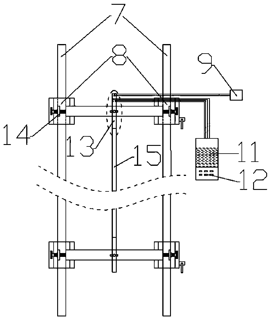
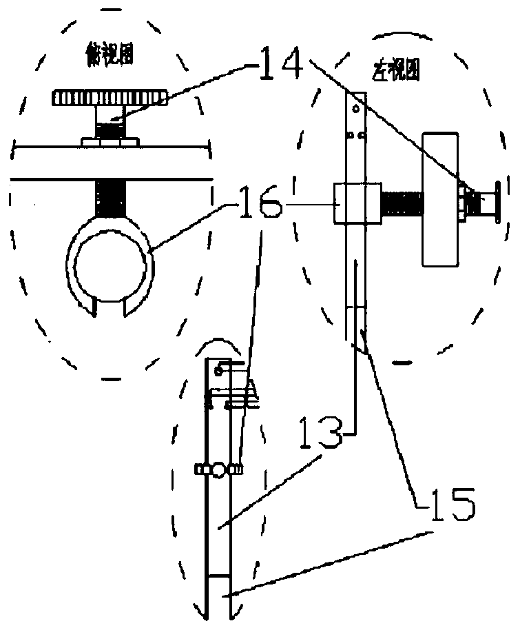
[0043] 40cm below the wire drawing furnace 2, facing the position of the outlet of the wire drawing furnace, the plexiglass tube 15 connected at both ends is vertically set, the length of the plexiglass tube 15 is 50cm, and the diameter is 4cm. The glass tube wall is oppositely provided with air-tight air holes, each air-tight air hole is sealed with a gas pipe, and the end of each air pipe communicates with a nitrogen source that provides nitrogen, and the nitrogen source controls the flow into the air pipe through the gas flow control device 9, so that The amount of nitrogen entering the plexiglass tube 15 meets the requirements of the air seal; four water vapor holes are arranged at intervals on the plexiglass tube wall below the air seal pore 10 cm away from the air seal pore, and each water steam hole is sealed and connected with a water vapor hole. Steam pipes, the ends of each water vapor pipe are in communicati...

Embodiment 2

[0046] Manufacturing method of low-loss optical fiber X2

[0047] 60cm below the wire drawing furnace 2 is facing the position of the outlet of the wire drawing furnace, vertically set the plexiglass tube 15 connected at both ends, the length of the plexiglass tube 15 is 60cm, the diameter is 6cm, and the organic glass tube 15 at the distance from the upper nozzle 20cm The glass tube wall is oppositely provided with gas-sealed air holes, each air-sealed air hole is sealed with a gas pipe, and the end of each gas pipe communicates with a nitrogen source that provides nitrogen, and the nitrogen source controls the flow into the gas pipe through the gas flow control device 9; Four water vapor pipe holes are arranged at intervals on the plexiglass tube wall 15cm away from the air seal air hole below the air seal air hole, each water steam hole is sealed and connected with a water vapor pipe, and the end of each water vapor pipe is connected to the water tank 11 communicates, and t...


PUM

PropertyMeasurementUnit
lengthaaaaaaaaaa
diameteraaaaaaaaaa

Abstract

The invention provides a manufacturing method of a low-loss optical fiber and manufacturing equipment. The manufacturing method comprises the following steps of: arranging a water vapor environment out of a fiber drawing furnace; and passing a hot optical fiber generated in the fiber drawing furnace through the water vapor environment after stretching out of the port of the fiber drawing furnace. According to the manufacturing method and corresponding manufacturing equipment provided by the invention, the crystal structure in the optical fiber is improved by way of water vapor annealing, so that the inner crystal structure is optimum, the rayleigh scattering of the optical fiber is reduced, and therefore, the loss is reduced to minimum 0.18db / km.

Description

technical field [0001] The invention relates to the field of optical fiber manufacturing, in particular to a method and equipment for manufacturing low-loss optical fibers. Background technique [0002] With the development of optical fiber technology, the long-distance transmission of optical fiber is getting bigger and bigger. Due to the high attenuation of the existing optical fiber, the transmission distance is short. In the long-distance transmission process, it is necessary to increase the relay station to enhance the signal. The price is expensive, and operators hope to have optical fibers that can reduce construction costs during long-distance transmission without affecting normal transmission loss. The loss of optical fiber is divided into intrinsic loss and manufacturing loss. Intrinsic loss is the inherent loss of optical fiber material and cannot be avoided. The manufacturing loss of optical fiber is produced in the process of manufacturing optical fiber, which ...

Claims


Application Information

Patent Timeline
Patent Type & Authority Patents(China)
IPC IPC(8): C03B37/10
Inventor 沈小平唐成蒋锡华祝君朱坤蒋小强甘发勇石碧波邓奋
Owner TONGDING INTERCONNECTION INFORMATION CO LTD
Learn More