Linkage balance beam-pumping unit

A beam pumping unit, balancing technology, applied in the direction of machine/engine, liquid variable capacity machinery, mechanical equipment, etc., can solve the problem of poor balance effect of the beam pumping unit, difficult to meet the requirements of production and processing, Due to the high requirements of screw manufacturing accuracy, the effect of obvious balance effect, smooth and stable oil pumping speed, and uniform load on the structure can be achieved.

Pending Publication Date: 2017-06-27
SOUTHWEST PETROLEUM UNIV
View PDF19 Cites 3 Cited by
  • Summary
  • Abstract
  • Description
  • Claims
  • Application Information

AI Technical Summary

Problems solved by technology

However, due to the large fluctuation of the load at the suspension point of the oil well and the generally poor balance effect of the beam pumping unit, the peak torque of the crank pin of the pumping unit is too large, and the power loss exceeds the standard. key
In order to solve the balance problem of the beam pumping unit, patents CN201420765751.8, CN201320762209.2, etc. have proposed the balance scheme of the screw guide rail, which controls the movement of the balance weight by installing the screw guide rail on the beam to achieve moment balance. It can improve the balance rate of the pumping unit, but the manufacturing precision of the screw rod is high. Large-scale pumping units have certain standards for the length of the screw rod, so it is difficult to meet the requirements of its production and processing.
Patents such as CN201620884807.0 propose to install a balance adjustment device at the end of the beam of the pumping unit. This solution increases the complexity of the design and poses certain safety hazards

Method used


Image

  • Linkage balance beam-pumping unit
  • Linkage balance beam-pumping unit
  • Linkage balance beam-pumping unit

Examples


Embodiment Construction

[0016] The embodiments of the present invention will be further described in detail in conjunction with the accompanying drawings, but the scope of protection of the present invention is not limited to the following description.

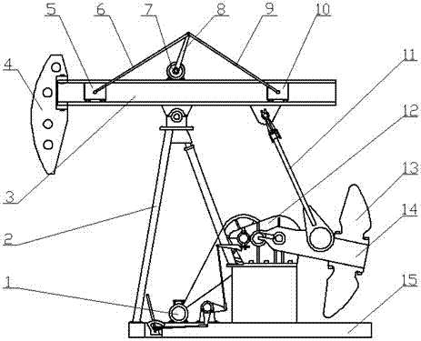
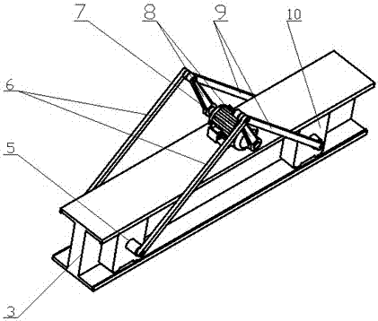
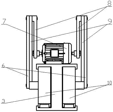
[0017] Such as figure 1 , figure 2 , image 3 As shown, a linkage balanced beam pumping unit of the present invention consists of an asynchronous motor 1, a bracket 2, a beam 3, a donkey head 4, a left double slider 5, a left double connecting rod 6, a double shaft motor 7, and a double crank 8, right double connecting rod 9, right double slide block 10, connecting rod 11, speed reducer 12, counterweight 13, crank 14, base 15 forms.

[0018] The biaxial motor 7 is fixedly installed above the bearing support position of the beam 3, with the output shaft of the biaxial motor 7 as the rotation center, the head end of the double crank 8 is connected through the pin shaft, and the other end of the double crank 8 is connected to the left side through th...


PUM


Abstract

The invention discloses a linkage balance beam-pumping unit, and belongs to the field of an oil production technique device, and especially relates to a linkage balance beam-pumping unit consisting of a slider-crank mechanism. The linkage balance beam-pumping unit is mainly composed of an asynchronous motor, a stand, a walking beam, a horse head, a left double-slider, a left double-linkage, a dual-axis motor, a dual-crank, a right double-linkage, a right double-slider, a reducer, a balancing weight block, a crank, and a base. The technical scheme is that the dual-axis motor is fixedly installed on the walking beam, and the output shaft of the motor is linked with the front end of the double-crank, and the other end of the double-crank is linked with the left and right double-linkages through a pin shaft; tail ends of the left and right double-linkages are equipped with the left and right double-sliders through the pin shaft, and the lower end of the slide block is provided with a roll wheel. The edge of the moving beam is welded with the side plate form a slide way; the left and right double-sliders are installed in the slide way, and the slide blocks are pushed to perform reciprocal rectilinear motion by the left and right double-linkages along with the length direction of the moving beam. The linkage balance beam-pumping unit is simple in structure, safe and reliable in use, and can adjust the balancing moment of the moving beam along with the change of the load at the suspending point of the pumping unit, thus the energy-saving and cost-reducing purpose is reached.

Description

technical field [0001] The invention belongs to the technical equipment field of petroleum exploitation, in particular to a linkage balanced beam pumping unit. Background technique [0002] The beam pumping unit is an important surface equipment for oil production in oil fields. It is simple in structure, stable and reliable, and is widely used in various oil fields. However, due to the large fluctuation of the load at the suspension point of the oil well and the generally poor balance effect of the beam pumping unit, the peak torque of the crank pin of the pumping unit is too large, and the power loss exceeds the standard. key. In order to solve the balance problem of the beam pumping unit, patents CN201420765751.8, CN201320762209.2, etc. have proposed the balance scheme of the screw guide rail, which controls the movement of the balance weight by installing the screw guide rail on the beam to achieve moment balance. In general, it can improve the balance rate of the pump...

Claims


Application Information

Patent Timeline
Patent Type & Authority Applications(China)
IPC IPC(8): E21B43/00F04B47/14
CPCE21B43/127F04B47/14
Inventor 王钰文侯勇俊邱忠诚方潘杜明俊钟方元
Owner SOUTHWEST PETROLEUM UNIV
Why Eureka
Try Eureka