

Method for performing two-segment treatment on solid waste incineration fly ash with cement kiln
A technology for solid waste and fly ash incineration, applied in combustion methods, incinerators, waste heat treatment, etc., can solve the problems of cumbersome disposal process, small disposal volume, high cost and high cost, and achieve the effect of mass disposal and cost reduction
- Summary
- Abstract
- Description
- Claims
- Application Information
AI Technical Summary
Problems solved by technology
Method used
Image

Examples
Embodiment 1
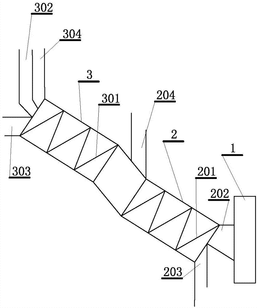
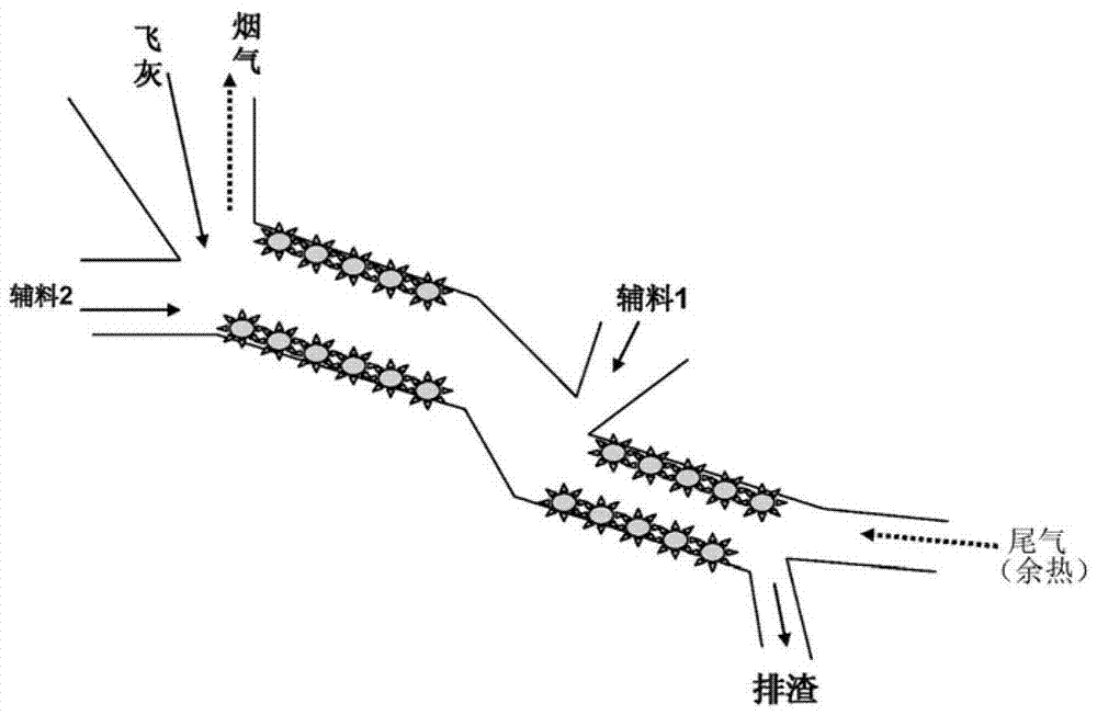
[0035] Such as figure 1As shown, a method for treating solid waste incineration fly ash by using a cement kiln in two stages, the device used in the method is a cement kiln and a fly ash treatment device connected to the rear end of the cement kiln, and the fly ash treatment device includes The first section of rotating steel cylinder and the second section of rotating steel cylinder, the rear end of the first section of rotating steel cylinder is connected to the front end of the second section of rotating steel cylinder, the first section of rotating steel cylinder and the second section of rotating steel cylinder are connected to each other connected, and the two sections of the rotary steel cylinder are equipped with propeller blades; the front end of the first section of the rotary steel cylinder is provided with an exhaust gas (waste heat) inlet and a slag discharge port, and the rear end of the first section of the rotary steel cylinder is provided with the first auxilia...
Embodiment 2
[0045] Such as figure 1 As shown, a method for treating solid waste incineration fly ash by using a cement kiln in two stages, the device used in the method is a cement kiln and a fly ash treatment device connected to the rear end of the cement kiln, and the fly ash treatment device includes The first section of rotating steel cylinder and the second section of rotating steel cylinder, the rear end of the first section of rotating steel cylinder is connected to the front end of the second section of rotating steel cylinder, the first section of rotating steel cylinder and the second section of rotating steel cylinder are connected to each other connected, and the two sections of the rotary steel cylinder are equipped with propeller blades; the front end of the first section of the rotary steel cylinder is provided with an exhaust gas (waste heat) inlet and a slag discharge port, and the rear end of the first section of the rotary steel cylinder is provided with the first auxili...
PUM
| Property | Measurement | Unit |
|---|---|---|
| Melting temperature | aaaaa | aaaaa |
Abstract
Description
Claims
Application Information