Shake and de-bubble structure and ultrasonic liquid concentrate test device

A testing device, liquid concentration technology, applied in the direction of measuring device, using sound wave/ultrasonic wave/infrasonic wave to analyze fluid, using sound wave/ultrasonic wave/infrasonic wave to conduct material analysis, etc. It can solve the problem of ultrasonic signal attenuation, probe damage life, large probe impact, etc. problem, achieve the effect of reducing direct impact and prolonging service life

Pending Publication Date: 2017-06-27
DONGGUAN ZHENGYANG ELECTRONICS MECHANICAL CO LTD
View PDF7 Cites 4 Cited by
  • Summary
  • Abstract
  • Description
  • Claims
  • Application Information

AI Technical Summary

Problems solved by technology

[0017] Although the above-mentioned ultrasonic liquid concentration test device for measuring liquid concentration can measure the urea concentration, the device cannot eliminate the factors that affect the measurement accuracy during the measurement process. , the probe is damaged or the service life is reduced; the temperature of the measured liquid is higher or the air bubbles caused by the addition of liquid are attac...

Method used


Image

  • Shake and de-bubble structure and ultrasonic liquid concentrate test device
  • Shake and de-bubble structure and ultrasonic liquid concentrate test device
  • Shake and de-bubble structure and ultrasonic liquid concentrate test device

Examples


Embodiment 1

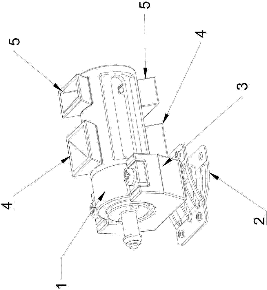
[0085] like Figure 1 to Figure 3 As shown, an ultrasonic liquid concentration detection device includes a probe 1 of an ultrasonic liquid concentration test device, a probe mounting base 3 , an oscillator 2 , a diversion jet 4 and a diversion jet 5 .

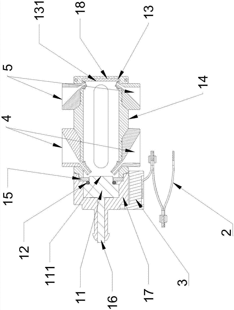
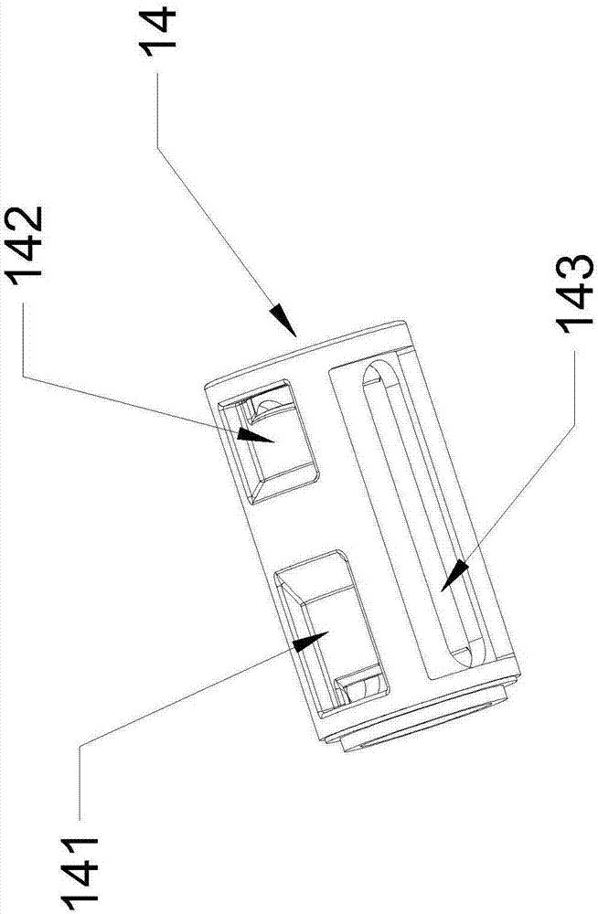
[0086] The probe 1 is designed as an integrated engineering plastic part, wherein the ultrasonic generator 11, the core component of the ultrasonic liquid concentration testing device, is wrapped by engineering plastics; another key functional part of the ultrasonic liquid concentration testing device, the ultrasonic reflection sheet 13 is inlaid Enter the column body 14.

[0087] Specifically, the sonotrode 11 is injection molded through an embedded mold through engineering plastics, and is inlaid into the sonotrode base 17, and the tail signal transmission line 16 of the sonotrode is also inlaid together; The mold is injection molded, and the embedded hardware material is an ultrasonic reflector.

[0088] The column body 14...

Embodiment 2

[0101] like Figure 1 to Figure 3 As shown, an ultrasonic liquid concentration detection device includes a probe 1 of the ultrasonic liquid concentration test device, a mounting base 3 for the probe 1 , an oscillating body 2 , a diversion jet body 4 and a diversion jet body 5 .

[0102] The probe 1 is designed as an integrated engineering plastic part, wherein the ultrasonic generator 11, the core component of the ultrasonic liquid concentration testing device, is wrapped by engineering plastics; another key functional part of the ultrasonic liquid concentration testing device, the ultrasonic reflection sheet 13 is inlaid Enter the column body 14.

[0103] Specifically, the sonotrode 11 is injection molded through an embedded mold through engineering plastics, and is inlaid into the sonotrode base 17, and the tail signal transmission line 16 of the sonotrode is also inlaid together; The mold is injection-molded, and the embedded hardware material is an ultrasonic reflection s...


PUM


Abstract

The invention discloses a shake structure of an ultrasonic liquid concentration test device. The shake structure comprises an upper connecting surface, a lower connecting surface and three end-to-end elastic pieces; the upper connecting surface is arranged at the bottom joint of a probe installation base, and the lower connecting surface is connected with a base used for fixing a probe and arranged at the bottom of the ultrasonic liquid concentration test device. The invention further discloses a de-bubble structure of the ultrasonic liquid concentration test device. The de-bubble structure comprises diversion jet bodies, each diversion jet body is composed of a funnel entry, a diversion inlet, a diversion channel, a jet exit and a weld line of the diversion jet body and a connection interface of a column. The invention further discloses an ultrasonic probe body part of the ultrasonic liquid concentrate test device, the ultrasonic probe body part comprises the probe forming the ultrasonic emission and acceptance device. The invention further discloses the ultrasonic liquid concentration test device, the probe of the ultrasonic liquid concentration test device is effectively protected, service life of the probe is prolonged, and meanwhile, test accuracy is improved.

Description

technical field [0001] The present invention relates to the technical field of concentration testing devices, in particular to an oscillating structure of a concentration testing device and a structure for removing air bubbles at the probe transmitting end and reflection end of the concentration testing device, and further relates to an oscillating structure of a liquid concentration testing device and Remove the bubble structure and liquid concentration test device at the probe launch end and reflection end of the liquid concentration test device, and further relate to an oscillation structure of an ultrasonic liquid concentration test device and remove the probe launch end and reflection end bubble structure of the ultrasonic liquid concentration test device. Liquid concentration test device. [0002] technical background [0003] Diesel engines have been widely used in all walks of life with higher horsepower. Compared with gasoline engines, the high temperature of diesel...

Claims


Application Information

Patent Timeline
IPC IPC(8): G01N29/02G01N29/22G01N29/24
CPCG01N29/02G01N29/225G01N29/24G01N2291/022G01N2291/02809G01N29/032G01N2291/0228G01N2291/045G01N29/222G01N2291/02433G01N29/024
Inventor 不公告发明人
Owner DONGGUAN ZHENGYANG ELECTRONICS MECHANICAL CO LTD
Why Eureka
Try Eureka