scan drive circuit
A scan drive circuit and scan drive technology, applied in digital memory information, instruments, static memory, etc., can solve the problems of scan drive circuit failure, threshold voltage Vth negative drift, low power consumption, etc., to prevent failure and leakage Effect
- Summary
- Abstract
- Description
- Claims
- Application Information
AI Technical Summary
Problems solved by technology
Method used
Image

Examples
Embodiment Construction
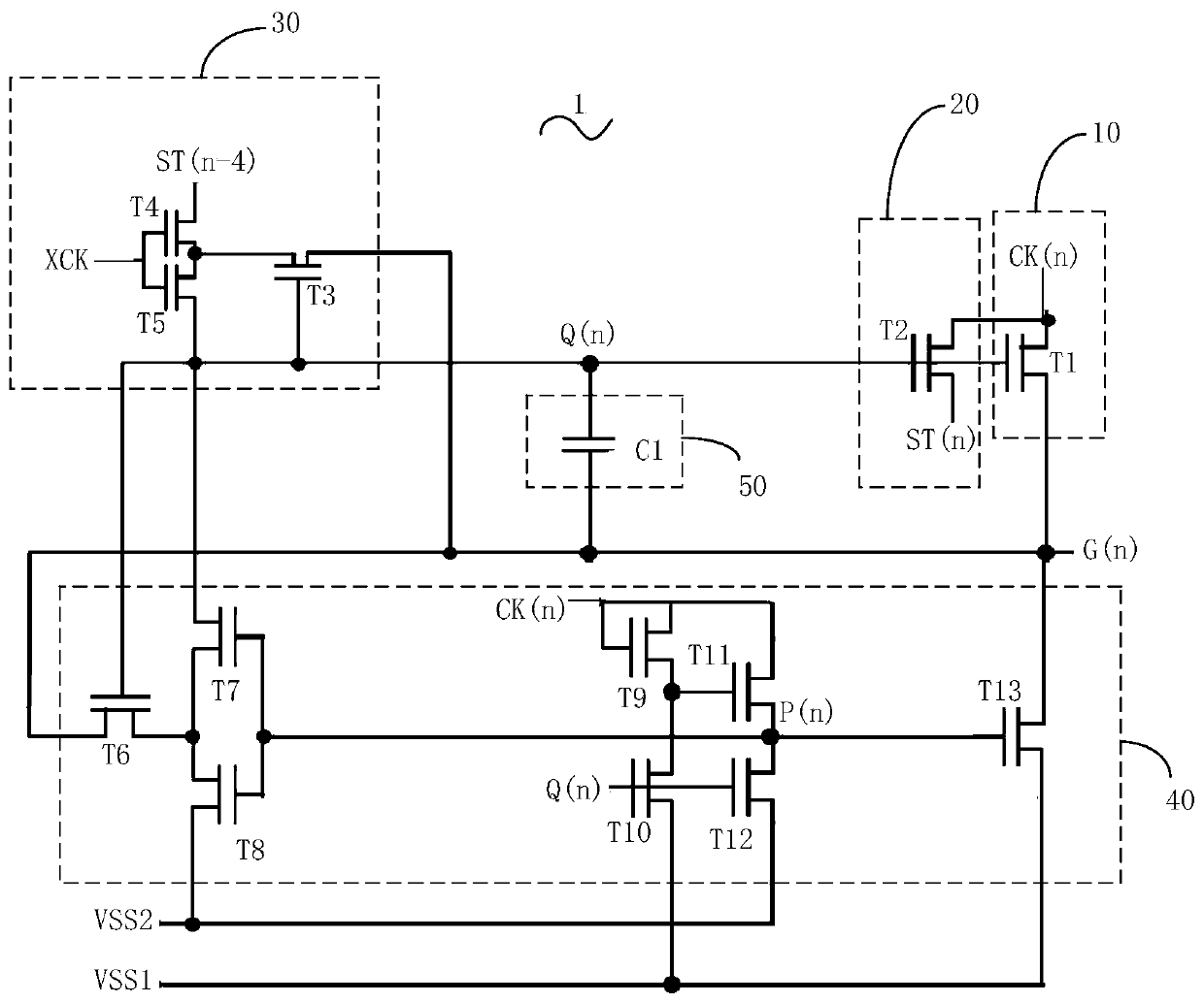
[0024] Please refer to figure 1 , is a schematic circuit diagram of the first embodiment of the scan driving circuit of the present invention. The scanning driving circuit includes several scanning driving units 1 connected in sequence, and each scanning driving unit 1 includes a scanning signal output terminal G(n), which is used to output a high-level scanning signal or a low-level scanning signal;
[0025] The pull-up circuit 10 is used to receive the clock signal CK(n) of the current stage and control the scanning signal output terminal G(n) to output a high-level scanning signal according to the clock signal CK(n) of the current stage;
[0026] The downlink circuit 20 is connected to the pull-up circuit 10, and is used to output a high-level level transmission signal ST(n);
[0027] The pull-up control circuit 30 is connected to the downlink circuit 20, and is used to charge the pull-up control signal point Q(n) to pull up the potential of the pull-up control signal poin...
PUM
 Abstract
Description
Claims
Application Information
 - R&D
- Intellectual Property
- Life Sciences
- Materials
- Tech Scout
- Unparalleled Data Quality
- Higher Quality Content
- 60% Fewer Hallucinations
Browse by: Latest US Patents, China's latest patents, Technical Efficacy Thesaurus, Application Domain, Technology Topic, Popular Technical Reports.
© 2025 PatSnap. All rights reserved.Legal|Privacy policy|Modern Slavery Act Transparency Statement|Sitemap|About US| Contact US: help@patsnap.com