
Airbag-based implantable wireless intracranial pressure monitoring system

A monitoring system and intracranial pressure technology, applied in the field of medical electronics, can solve the problems of endangering the health of patients, increasing the risk of infection of patients, and the volume of hydraulic pressure sensors cannot be made too small, so as to reduce the risk of infection

Active Publication Date: 2017-06-30
TSINGHUA UNIV
View PDF6 Cites 10 Cited by
  • Summary
  • Abstract
  • Description
  • Claims
  • Application Information

AI Technical Summary

Problems solved by technology

Monitoring intracranial pressure based on a hydraulic sensor has the following disadvantages: This method requires the hydraulic sensor to be in direct contact with the intracranial fluid, which increases the difficulty of isolating the circuit components in the implanted device from the liquid, and easily leads to the failure of the electronic components in the implanted device. Contact with liquid will cause damage, and the direct contact of electronic components with intracranial fluid will also endanger the health of the monitored patient; this method requires that the hydraulic pressure sensor be directly placed on the part of the brain to be measured, and the volume of the hydraulic pressure sensor itself often cannot be made It is very small, so the opening in the skull will be relatively large during implantation surgery, increasing the risk of infection for the patient

Method used


Image

  • Airbag-based implantable wireless intracranial pressure monitoring system
  • Airbag-based implantable wireless intracranial pressure monitoring system
  • Airbag-based implantable wireless intracranial pressure monitoring system

Examples


Embodiment Construction

[0034] The embodiments of the present invention will be described in detail below with reference to the accompanying drawings and examples.

[0035] The present invention provides an implantable wireless intracranial pressure monitoring system based on a balloon. like figure 1 As shown, the system consists of three parts: an intracranial pressure implantation monitoring device 100, an extracorporeal intracranial pressure data recorder 200, and an extracorporeal data management terminal 300 for intracranial pressure data storage and management.

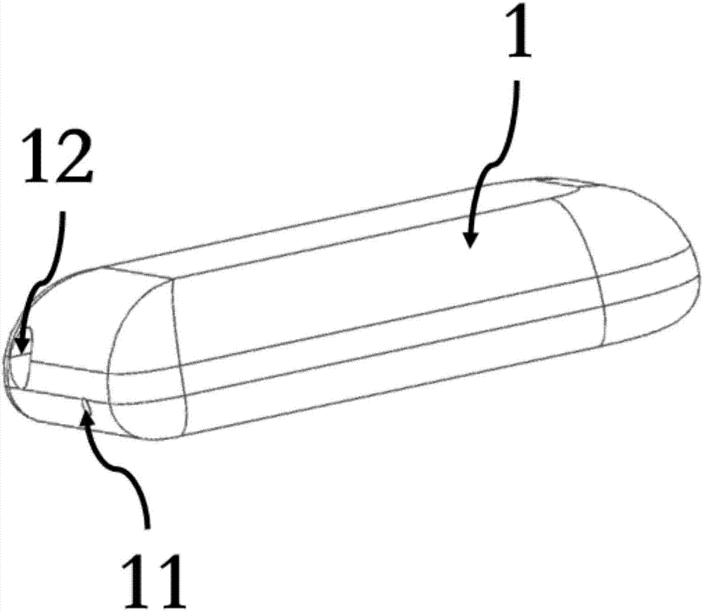
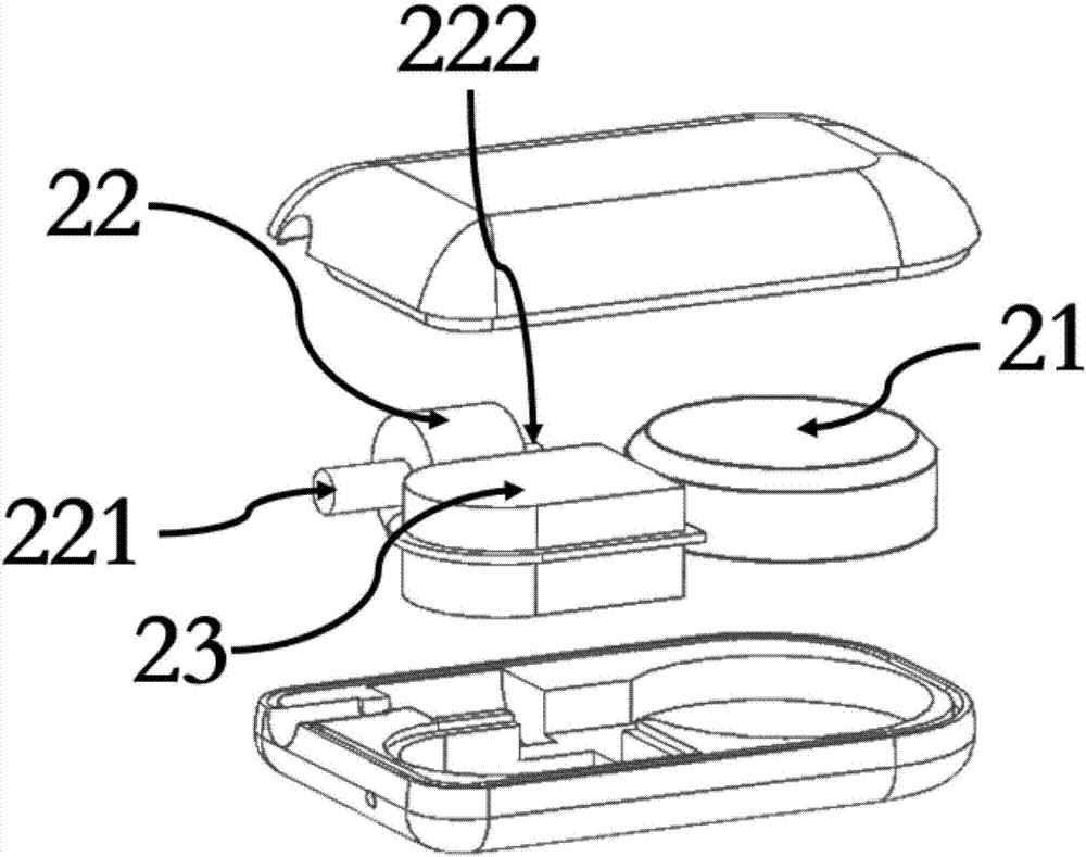
[0036] Wherein, the intracranial pressure implantation monitoring device 100 includes four major parts: a casing 1 , structures and circuits in the casing, a gas conduit, and a balloon 4 .

[0037] The casing 1 of the intracranial pressure implantation monitoring device 100 is made of a material with biocompatibility. Since the outer surface of the casing 1 is in direct contact with human tissue and body fluids, it needs to be made i...


PUM


Abstract

The invention relates to an airbag-based implantable wireless intracranial pressure monitoring system, comprising three parts: an intracranial pressure implantation monitoring device, an in vitro intracranial pressure data recorder, and a data management terminal, wherein the intracranial pressure implantation monitoring device comprises a shell, a gas conduit, an airbag, a gas check valve, a gas absolute pressure sensor, a temperature sensor, a control circuit, a wireless transceiver circuit, a battery, and an antenna, and the in vitro intracranial pressure data recorder comprises an antenna, a wireless transceiver circuit, a gas absolute pressure sensor, a control and data processing circuit, a display screen, and a battery. The in vitro intracranial pressure data recorder receives intracranial pressure data and intracranial temperature data measured by the intracranial pressure implantation monitoring device. The data is processed and then displayed on the display screen in real time, and the data management terminal can store and manage the intracranial pressure data for a long time. The method provided by the invention overcomes the shortcoming that the non-implantable intracranial pressure measurement method is easy to lead to infection. The airbag-based pressure measurement method has the advantages that a small opening is formed in the skull and the circuit is easily isolated from liquid.

Description

technical field [0001] The invention belongs to the technical field of medical electronics, and relates to an intracranial pressure measurement system device, in particular to an implanted wireless intracranial pressure monitoring system based on a balloon. Background technique [0002] Increased intracranial pressure (ICP, full name intracranial pressure) is a reflection of intracranial disease or intracranial secondary disease. If intracranial pressure data can be continuously monitored and the phenomenon of increased intracranial pressure can be detected in time, it is beneficial to early Find and timely treatment of increased intracranial pressure and intracranial disease, and improve the efficacy. When measuring intracranial pressure, the probe can be placed in different locations within the skull: epidural, subdural, subarachnoid, brain parenchyma, ventricle, etc. When the probe is placed in different positions, the measurement effect is different. There are two type...

Claims


Application Information

Patent Timeline
IPC IPC(8): A61B5/03
CPCA61B5/031A61B5/6846A61B5/6868
Inventor 姜汉钧王志华吴泽亮张春李福乐
Owner TSINGHUA UNIV
Learn More