
Liquid material vaporization apparatus

A technology for liquid materials and gasification devices, which is applied in boiling devices, gaseous chemical plating, metal material coating processes, etc., and can solve the problems of difficulty in stably generating material gas and inability to stably gasify

Active Publication Date: 2017-06-30
HORIBA STEC CO LTD
View PDF5 Cites 3 Cited by
  • Summary
  • Abstract
  • Description
  • Claims
  • Application Information

AI Technical Summary

Problems solved by technology

As a result, liquid transport to the vaporizer and vaporization in the vaporizer cannot be performed stably, and as a result, there is a problem that it is difficult to stably generate material gas.

Method used


Image

  • Liquid material vaporization apparatus
  • Liquid material vaporization apparatus
  • Liquid material vaporization apparatus

Examples


Embodiment Construction

[0034] One embodiment of the liquid material vaporization device of the present invention will be described below with reference to the drawings.

[0035] The liquid material vaporization device 100 of this embodiment is, for example, assembled in an optical fiber manufacturing device and used in an optical fiber manufacturing process. In addition, for example, it can be incorporated into a semiconductor manufacturing device and used in a semiconductor manufacturing process.

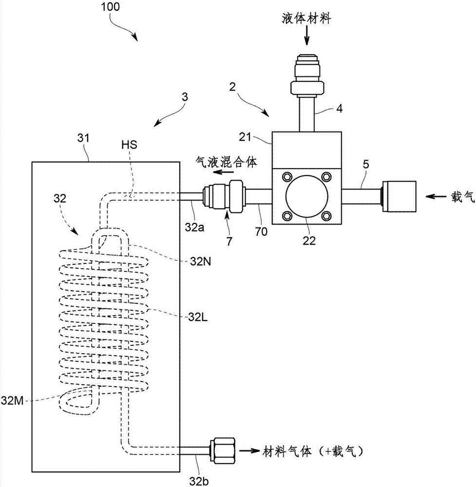
[0036] Specifically, as figure 1 As shown, the liquid material vaporization device 100 includes: a gas-liquid mixing part 2, which mixes the liquid material and a carrier gas as a gas to form a gas-liquid mixture; and a gasification part 3, which heats the gas-liquid mixture and utilizes The carrier gas guides out the material gas obtained by vaporizing the liquid material.

[0037] In addition, the liquid material is OMCTS (octamethylcyclotetrasiloxane, boiling point 175° C.), TEOS (tetraethoxysilane,...


PUM

PropertyMeasurementUnit
boiling pointaaaaaaaaaa

Abstract

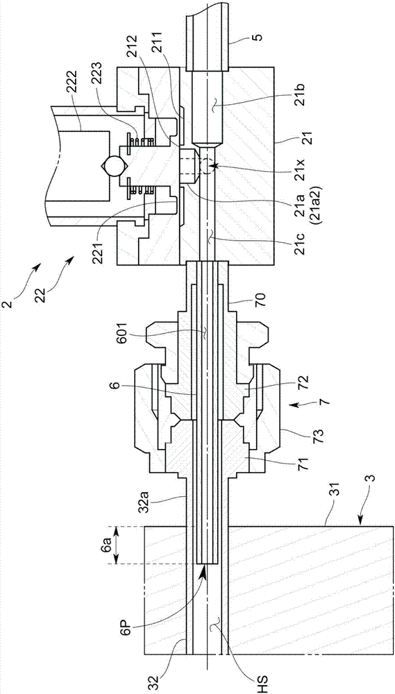
In order to eliminate liquid accumulation occurring between a gas-liquid mixing part and a vaporization part to stably perform liquid feeding to the vaporization part and vaporization in the vaporization part, a liquid material vaporization apparatus includes: a gas-liquid mixing part (2) adapted to mix a liquid material and gas to produce a gas-liquid mixture; and a vaporization part (3) adapted to heat the gas-liquid mixture to vaporize the liquid material. In addition, the gas-liquid mixing part (2) has a gas-liquid mixture lead-out pipe (6) for leading out the gas-liquid mixture, the vaporization part (3) has a heating flow path HS for heating the gas-liquid mixture, and a lead-out port (6P) of the gas-liquid mixture lead-out pipe (6) is arranged in the heating flow path HS.

Description

technical field [0001] The invention relates to a liquid material gasification device. Background technique [0002] As shown in Patent Document 1, a conventional liquid material vaporization device is a device in which a liquid material and a carrier gas are mixed while controlling the flow rate in a gas-liquid mixing unit in a control valve equipped with a liquid flow rate control function. , and the gas-liquid mixture at this time is released from the nozzle part formed near the flow control part, and the liquid material is decompressed and vaporized. [0003] Patent Document 1: Japanese Patent Laid-Open Publication No. 2001-156055 [0004] Furthermore, since it is difficult to generate a large flow rate of material gas in the above-described liquid material vaporization device, it is conceivable to use it together with a vaporizer especially in a large flow rate application. [0005] However, since the flow channel expands just behind the nozzle portion of the gas-liqu...

Claims


Application Information

Patent Timeline
Patent Type & Authority Applications(China)
IPC IPC(8): C23C16/448B01F23/80
CPCC23C16/4481B01B1/00B01D1/02B01D1/14B01F23/806B01F23/811
Inventor 伊东丈智井上正规
Owner HORIBA STEC CO LTD
Learn More