Real-time monitoring system for bottom surface of bridge

A real-time monitoring system and bottom surface technology, applied to bridges, bridge parts, bridge construction, etc., can solve problems such as easy leakage, large property loss, and leakage, and achieve the effect of ensuring stability, avoiding inclination, and ensuring balance

Active Publication Date: 2017-06-30
CHANGAN UNIV
View PDF7 Cites 8 Cited by
  • Summary
  • Abstract
  • Description
  • Claims
  • Application Information

AI Technical Summary

Problems solved by technology

At present, the commonly used equipment for bridge deformation monitoring are: conventional ground measurement equipment, GPS bridge displacement detection equipment, and radar deformation measurement equipment; Timely response and treatment will result in huge property losses and heavy casualties, so we need to monitor the deformation of the bridge in real time to achieve the purpose of early treatment
[0003] A real-time monitoring system for bridge deformation is disclosed in the publication number CN 105890663 A. The invention includes a monitoring room and a bridge deck; the bottom of the bridge deck is connected with a bridge deck support beam; the two ends of the bridge deck support beam bottom are connected with bridge piers; One side of the bridge deck is equipped with bridge deck monitoring point sensors; the monitoring room is associated with the bridge deck monitoring point sensors; both sides of the bridge deck are provided with flanges; the flanges are in a horizontal state; the inside of the monitoring room is equipped with a data processor; An evaluation worker is set on one side of the data processor; the top surface of the evaluation worker is connected to a console; bridge monitoring point sensors are set at both ends of the front of the bridge deck support beam; bridge pier monitoring point sensors are set on the side of the bridge pier near the bottom ;The side of the other pier near the bottom is equipped with a displacement gauge; although this structure has obtained a good detection effect, it cannot detect the interior and all-round detection, which makes it prone to mistakes
[0004] In the publication number CN 105973452 A, a remote bridge vibration monitoring system includes a laser transmitter, an optical fiber coupler, an optical fiber, a stepping motor, a plane mirror, an optical fiber collimator, a photoelectric detector and a signal transmission module, and a laser transmitter The emitted laser light is dispersed into multiple laser beams after passing through the fiber coupler. The first laser beam is irradiated on the rotatable plane mirror through the optical fiber, and the laser beam is reflected on the plane mirror. The laser light is sent to multiple photodetectors respectively through the optical fiber; the photodetector also receives the scattered signal of the laser light on the bottom surface of the bridge and sends the signal together with the laser signal received from the optical fiber to the signal sending module; To obtain the information of the bridge, but it has not realized the all-round detection of the bridge, so it is also prone to mistakes.

Method used


Image

  • Real-time monitoring system for bottom surface of bridge
  • Real-time monitoring system for bottom surface of bridge

Examples


Embodiment 1

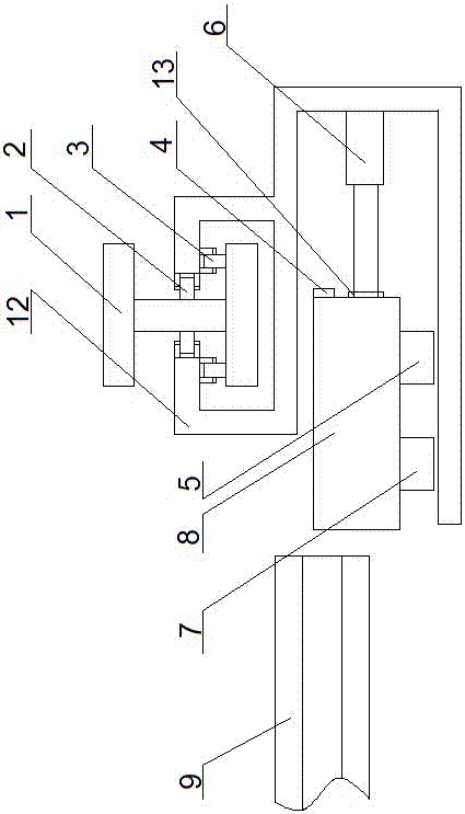
[0034] A bridge bottom real-time monitoring system, comprising a track mechanism arranged on the bridge bottom, and a detection mechanism arranged on the track mechanism for detecting the actual condition of the bridge bottom;

[0035] The track mechanism includes a main track 1 arranged on the bottom surface of the bridge for walking, and an auxiliary track 9 that cooperates with the main track 1 for detecting the bottom surface of the bridge;

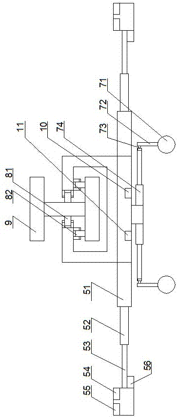
[0036] The detection mechanism includes a walking mechanism, and a mechanical arm 6 arranged on the walking mechanism is arranged on the walking mechanism in cooperation with the mechanical arm 6, and is used to cooperate with the auxiliary detection mechanism with the auxiliary track;

[0037] The auxiliary detection mechanism includes an auxiliary walking mechanism, a balance module arranged on the lower part of the auxiliary walking mechanism for monitoring the module, a telescopic module arranged on the auxiliary walking mechanism an...

Embodiment 2

[0047] The traveling wheel set comprises a horizontal traveling wheel 3 and a vertical traveling wheel 2 arranged on the I-shaped steel track;

[0048] The auxiliary traveling mechanism includes an auxiliary traveling seat 8, which is arranged on the auxiliary traveling seat 8 for driving the auxiliary traveling wheel set;

[0049] The main track adopted in this embodiment is an I-steel track arranged along one side of the bottom surface of the bridge, and the auxiliary track is an auxiliary I-steel track arranged on the bridge hole surface of the bottom surface of the bridge and perpendicular to the I-steel track; To ensure the stability of the structure and prevent the device from falling due to wind, the walking mechanism adopted includes a walking seat, a walking wheel set arranged on the upper part of the walking seat, and a walking wheel set arranged in the walking seat. Auxiliary walking mechanism, the mechanical arm that is arranged on the walking seat and cooperates w...

Embodiment 3

[0051] The vertical height of the auxiliary I-shaped steel guide rail is lower than that of the main I-shaped steel guide rail.

[0052] In this embodiment, the balance module is adopted to include a MEMS gyroscope and a MEMS accelerometer arranged on the auxiliary walking seat, and the auxiliary telescopic rods arranged on both sides of the auxiliary walking seat are arranged at the ends of the auxiliary telescopic rods through adjustment. The balance pole set by the motor, the balance ball set at the lower end of the balance pole; the data monitoring is realized through the gyroscope and the accelerometer, and then fed back to the control chip on the balance module, which realizes dynamic balance, and the telescopic module adopted It includes a first-stage telescopic rod, a second-stage telescopic rod arranged on the first-stage telescopic rod, and a third-stage telescopic rod arranged on the second-stage telescopic rod; through hierarchical expansion and contraction, it is e...


PUM


Abstract

The invention provides a real-time monitoring system for a bottom surface of a bridge. The real-time monitoring system comprises a rail mechanism which is arranged at the bottom surface of the bridge, and a detection mechanism which is arranged on the rail mechanism and is used for detecting the actual condition of the bottom surface of the bridge; a main rail is arranged on the bottom surface of the bridge and a secondary rail is arranged at the lower part of a bridge opening and the detection mechanism arranged on the main rail is used for bearing a secondary detection mechanism; the arranged main rail is higher than the vertical height of the secondary rail; the detection mechanism moves on the main rail and the secondary detection mechanism is laid on the secondary rail along the movement direction of the main rail, so that a monitoring test is carried out in all directions and a phenomenon that a detection period is long is avoided; and acquired data information is returned back to a central control room and is subjected to rapid comparison and analysis, so that the problems of the bottom of the bridge are rapidly compared.

Description

technical field [0001] The invention relates to the technical field of bridge detection devices, in particular to a real-time monitoring system for the bottom surface of a bridge. Background technique [0002] Bridge deformation monitoring is of great significance for mastering the health of bridges and ensuring bridge safety. At present, the commonly used equipment for bridge deformation monitoring are: conventional ground measurement equipment, GPS bridge displacement detection equipment, and radar deformation measurement equipment; Timely response and treatment will result in huge property losses and heavy casualties, so we need to monitor the deformation of the bridge in real time to achieve the purpose of early treatment. [0003] A real-time monitoring system for bridge deformation is disclosed in the publication number CN 105890663 A. The invention includes a monitoring room and a bridge deck; the bottom of the bridge deck is connected with a bridge deck support beam...

Claims


Application Information

Patent Timeline
IPC IPC(8): E01D19/10
CPCE01D19/106
Inventor 宫赛唐鹏
Owner CHANGAN UNIV
Why Eureka
Try Eureka