
Positioning and connecting device of grid arch frame and feet-lock anchor rods and construction method thereof

A technology of locking foot bolts and connecting devices, which is applied to the installation of bolts, earthwork drilling, mining equipment, etc., and can solve the problem of inability to realize simultaneous or close-packed grid arches, support and locking foot bolts. Reliable, unable to effectively control vault settlement and other issues, to achieve high ultimate bearing capacity, stable ultimate bearing capacity, and convenient on-site construction

Active Publication Date: 2017-06-30
TONGJI UNIV
View PDF6 Cites 5 Cited by
  • Summary
  • Abstract
  • Description
  • Claims
  • Application Information

AI Technical Summary

Problems solved by technology

[0003] However, the existing grid arches and lock foot anchors are mostly connected by spot welding or short welds, and the connecting parts are mostly made of steel plates or steel bars. Bearing capacity, it is easy to cause local failure of primary support
Secondly, most of the existing connection methods are based on on-site welding. When there are unfavorable construction conditions such as weak surrounding rock, high dust concentration, and large water seepage in the tunnel, the welding quality is difficult to guarantee, and it is easy to lose welding and leakage, and the connection reliability is low.
Third, the position of the existing connectors protrudes from both sides of the grid arch, and there is space conflict with other primary support components such as steel mesh and longitudinal connecting bars, which is not conducive to rapid construction on site; in dangerous areas such as Matoumen , cannot realize simultaneous or close-packed grid arches
The above factors lead to unreliable connection between the primary support and the locking foot bolt, inconvenient construction, and failure to effectively control the settlement of the vault

Method used


Image

  • Positioning and connecting device of grid arch frame and feet-lock anchor rods and construction method thereof
  • Positioning and connecting device of grid arch frame and feet-lock anchor rods and construction method thereof
  • Positioning and connecting device of grid arch frame and feet-lock anchor rods and construction method thereof

Examples


Embodiment

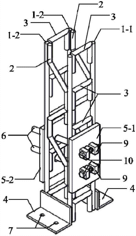
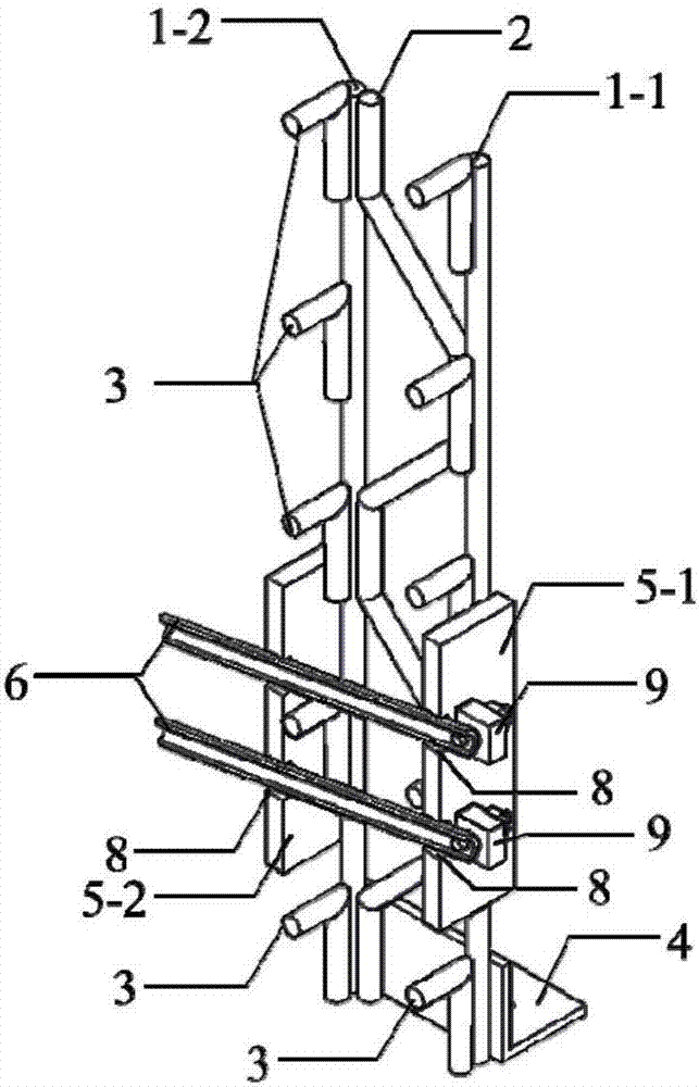
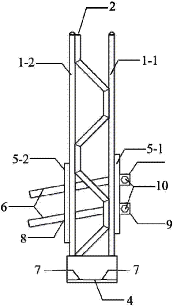
[0032] Such as Figure 1 to Figure 7 As shown in the figure, a positioning and connection device for a grid arch and a lock foot anchor rod and its application method include the grid arch main reinforcement 1-1 and 1-2, the horizontal strip 3 and the positioning connection steel plate 5-1 and 5-2 is connected by double-sided welding, and the bolt positioning block 9 with the bolt hole is installed on both sides of the round-end anchor hole 8 of the positioning connection steel plate 5-1 away from the side of the surrounding rock by surrounding welding, and the tail end is opened. Lock foot bolt 6 passes through the grid arch main reinforcement 1-1 and 1-2 along the round-end bolt hole and drives into the surrounding rock, and the pressure-bearing large hexagonal high-strength bolt 10 passes through the bolt hole of the bolt positioning block 9 And the opening at the tail end of the locking foot anchor rod 6 to realize the locking of the relative position of the locking foot a...


PUM


Abstract

The invention relates to a positioning and connecting device of a grid arch frame and feet-lock anchor rods and a construction method thereof. The positioning and connecting device is used for connecting the grid arch frame and the feet-lock anchor rods rapidly and reliably and comprises two positioning and connecting steel plates which welded to the side close to surrounding rock and the side far from the surrounding rock of the grid arch frame correspondingly. The tail ends of the feet-lock anchor rods penetrates through anchor rod holes formed in the positioning and connecting steel plate on the side close to the surrounding rock and the positioning and connecting steel plate on the side far from the surrounding rock in sequence and are fixed through fixing assemblies arranged on the positioning and connecting steel plate on the side far from the surrounding rock; and the drill ends of the feet-lock anchor rods are inserted into the surrounding rock to be fixed. The positioning and connecting steel plates are welded between two main steel bars of the grid arch frame. Compared with the prior art, the positioning and connecting device has the advantages of avoiding local damage and space conflicts, improving stability and bearing capacity, reliable connection, convenient and rapid operation and the like.

Description

technical field [0001] The present invention relates to the field of initial support grid arch frame and lock-foot anchor rod construction in step-by-step excavation construction of underground excavation method, in particular to a positioning connection device for grid arch frame and lock-foot anchor rod and its construction method. Background technique [0002] In the step-by-step excavation construction of underground excavation tunnels, in order to control the settlement of the vault and the convergence of the arch waist, it is necessary to set up the initial support structure in time. The bearing capacity is high, and the amount of steel is small. It is a more economical and reasonable form of primary support when used in conjunction with shotcrete. Since the surrounding rock at the step interface is loose and will be excavated, it cannot provide support for the grid arch. Therefore, the grid arch of the upper initial support must be reliably anchored to the surroundin...

Claims


Application Information

Patent Timeline
IPC IPC(8): E21D20/00
CPCE21D20/00E21D20/003
Inventor 于正周顺华宫全美杨龙才肖军华陕耀
Owner TONGJI UNIV
Learn More