
Forced oil lubricated high-speed rolling bearing test bench

A high-speed rolling and bearing test technology, which is applied in the direction of mechanical bearing testing, etc., can solve the problems of decreased lubrication performance and limited operating speed, and achieve the effects of preventing inaccurate detection, realizing cooling and recycling, and ensuring cleanliness

Active Publication Date: 2017-06-30
EAST CHINA JIAOTONG UNIVERSITY
View PDF13 Cites 3 Cited by
  • Summary
  • Abstract
  • Description
  • Claims
  • Application Information

AI Technical Summary

Problems solved by technology

[0004] In order to overcome the problems of the limited running speed of the rolling bearing test bench described in the background technology and the degradation of the lubricating performance of the lubricant due to the high speed, the present invention provides a pressure-lubricated high-speed rolling bearing test bench. The device adopts two pairs of bearings arranged side by side for support The structure of the rotating shaft, and the oil pump is used to supply the lubricating oil required by the high-speed rolling bearing test bench, thereby ensuring the high-speed operation accuracy of the rolling bearing test bench and realizing the cooling and recycling of the lubricating oil, thereby improving the lubrication performance of the lubricant

Method used


Image

  • Forced oil lubricated high-speed rolling bearing test bench
  • Forced oil lubricated high-speed rolling bearing test bench
  • Forced oil lubricated high-speed rolling bearing test bench

Examples


Embodiment Construction

[0013] Below in conjunction with accompanying drawing and embodiment the present invention will be further described:

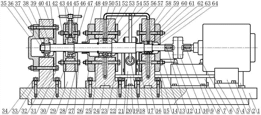
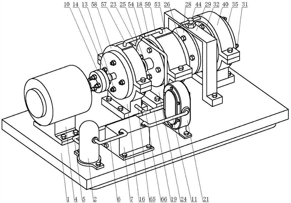
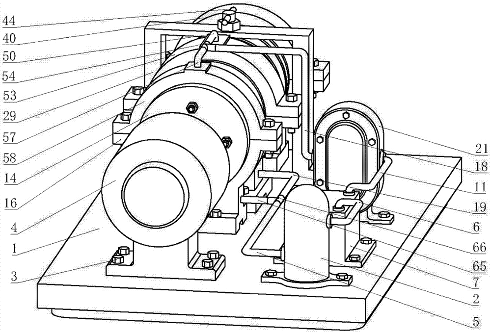
[0014] as attached figure 1 , attached figure 2 And attached image 3 As shown, the present invention includes base 1, filter 2, fastening bolt I3, motor 4, oil pipe I5, oil pipe II6, oil tank 7, fastening bolt II8, flat key I9, coupling 10, oil pipe III11, flat key II12 , fastening bolt Ⅲ13, bearing end cover Ⅰ14, fastening bolt Ⅳ15, bearing seat lower part Ⅰ16, bearing end cover Ⅱ17, oil pipe Ⅳ18, oil pipe Ⅴ19, fastening bolt Ⅴ20, oil pump 21, fastening bolt Ⅵ22, bearing end cover Ⅲ23, Lower part of bearing seat Ⅱ24, fastening bolt Ⅶ25, bearing end cover Ⅳ26, fastening bolt Ⅷ27, loading bearing end cover Ⅰ28, bracket 29, loading bearing end cover Ⅱ30, fastening bolt Ⅸ31, test bearing end cover Ⅰ32, test bearing seat lower part 33, fastening bolt X34, test bearing end cover II35, rotating shaft 36, round nut 37, test bearing 38, positioning sleeve I39, u...


PUM


Abstract

The invention discloses a forced oil lubricated high-speed rolling bearing test bench. The forced oil lubricated high-speed rolling bearing test bench is composed of a base, a filter, an oil pump, an oil tank, oil pipes, tee interfaces, a motor, a coupling, a rotation shaft, flat keys, positioning shaft sleeves, bearings, a loading bearing, a test bearing, oil spray rings, bearing block lower parts, bearing block upper parts, a loading bearing block, snap rings, a round nut, bearing end covers, felt collar oil seals, a threaded loading rod, a bracket, a washer, a fastening bolt and the like. According to the forced oil lubricated high-speed rolling bearing test bench, a structure according to which two pairs of bearings are arranged side by side to support the rotation shaft is adopted; the oil pump is adopted to provide lubricating oil for the high-speed rolling bearing test bench; the filter is adopted to purify the lubricating oil; and therefore, the high-speed and stable operation of the test bench can be realized; and the cooling cyclic utilization of the lubricating oil is realized, so that the lubrication performance of the lubricating oil can be improved. Compared with an existing bearing test bench device, the device of the invention has the advantages of reliable performance in high-speed operation, convenient disassembly and simple and convenient operation, and is especially suitable for high-speed rolling bearing tests and other conditions where bearings generate a lot of heat.

Description

technical field [0001] The invention relates to a rolling bearing test stand, in particular to a pressure lubricated high-speed rolling bearing test stand. Background technique [0002] Rolling bearing is one of the important basic parts in industrial machinery and equipment, and its working performance directly determines the operation performance of the whole machine. Rolling bearings are usually composed of four parts: outer ring, inner ring, rolling element and cage. Its function is to support the rotating parts in the machine to reduce the friction in its motion and ensure the rotation accuracy of the rotating parts. With the continuous improvement of various mechanical precision, rapidity and reliability requirements, it is particularly important to conduct experimental research on rolling bearings, so it is necessary to design a rolling bearing test bench that can adapt to high-speed conditions. [0003] At present, most of the rolling bearing test benches on the mar...

Claims


Application Information

Patent Timeline
Patent Type & Authority Applications(China)
IPC IPC(8): G01M13/04
CPCG01M13/04Y02T10/86
Inventor 涂文兵何海斌刘乐平罗丫王朝兵周生通
Owner EAST CHINA JIAOTONG UNIVERSITY
Learn More