Automatic wafer conveying machine and method

A wafer, automatic technology, applied in the manufacture of conveyor objects, electrical components, semiconductor/solid-state devices, etc., can solve problems such as wafer breakage and damage, and achieve the effect of convenient handling

Active Publication Date: 2017-06-30
憬承光电科技(厦门)有限公司
View PDF4 Cites 5 Cited by
  • Summary
  • Abstract
  • Description
  • Claims
  • Application Information

AI Technical Summary

Problems solved by technology

However, when transporting the temporary wafer storage cassette storing the wafers to the next workstation, the operator often forgets to release the stop member to limit the wafers, which causes the mechanical arm to forcibly take out the wafers from the opening, resulting in Cracked and damaged by the round hitting the stop member
In addition, the slot pitch of the temporary wafer storage cassette is larger than the thickness of the wafer, and the accommodation space of the temporary wafer storage cassette is larger than the area of ​​the wafer, so the wafer will still be in the temporary storage cassette during the transportation process. Shake inside, and collide with the wafer temporary storage cassette, which will also cause wafer breakage and damage

Method used


Image

  • Automatic wafer conveying machine and method
  • Automatic wafer conveying machine and method
  • Automatic wafer conveying machine and method

Examples


Embodiment

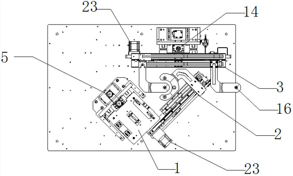
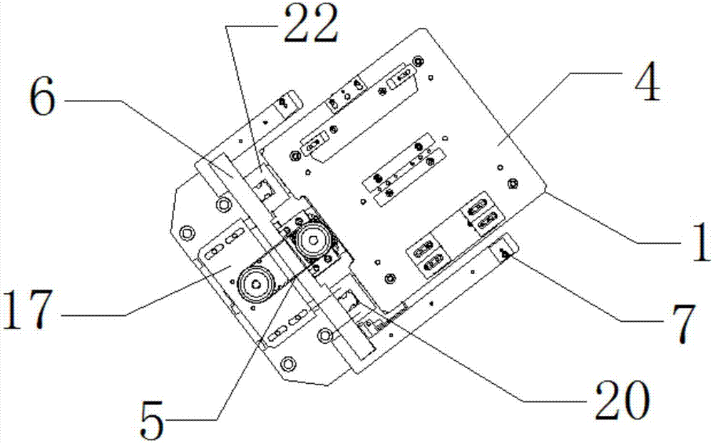
[0045] refer to Figure 1 to Figure 10 , an automatic wafer transfer machine, the automatic wafer transfer machine includes a cassette module 1, a first robot arm module 2 for extracting and storing wafers, and a wafer on the first robot arm module for transferring To the second mechanical arm module 3 of the workbench, wherein:

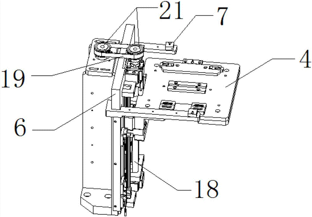
[0046] The cassette module includes a working platform 4 for installing the cassette, a cassette lifting table transmission device 5 for lifting and lowering in the Z-axis direction, and a cassette module fixing frame 6. Optical fiber sensors 7 on both sides of the platform for scanning wafers in the cassette;

[0047] The first mechanical arm module includes a first mechanical arm fixing base 8 provided with a linear slide rail 27, a linear transmission device 9 on one side of the first mechanical arm fixing base, and a first mechanical arm 10 reciprocating on the linear sliding rail. , the end of the first robotic arm is provided with a "C"-shape...


PUM


Abstract

The invention discloses an automatic wafer conveying machine and method, and the conveying machine is characterized in that the conveying machine comprises a clamping module group, a first mechanical arm module group for storing a wafer, and a second mechanical arm module group for conveying the wafer on the first mechanical arm module group to a workbench. The conveying machine can complete the conveying of the wafer in a better way, and multiple limiting and induction units are disposed among the parts, and can prevent the wafer from being damaged in a conveying process.

Description

technical field [0001] The invention relates to the field of semiconductor manufacturing, in particular to a wafer transfer machine transfer method. Background technique [0002] Semiconductor wafers will be transported to different workstations due to the need to go through various processes and to cooperate with process equipment. In order to facilitate the handling of wafers and avoid impacts from external forces, multiple wafers are stored in temporary wafer storage cassettes. [0003] Generally speaking, a plurality of slots arranged layer by layer are arranged in the temporary wafer storage cassette to accommodate a plurality of wafers horizontally, and one side of the cassette has an opening for loading and unloading of the wafers. Furthermore, a stop member is also provided at the opening to prevent the wafer from slipping out during transport. However, when transporting the temporary wafer storage cassette storing the wafers to the next workstation, the operator o...

Claims


Application Information

Patent Timeline
Patent Type & Authority Applications(China)
IPC IPC(8): H01L21/677
CPCH01L21/67706H01L21/67736H01L21/67766H01L21/67778
Inventor 李涛陈曦王广禄
Owner 憬承光电科技(厦门)有限公司
Why Eureka
Try Eureka