Clamping mechanism suitable for clamping flat surface or curved surface

A technology of clamping mechanism and curved surface, which is applied in the direction of clamping, metal processing machinery parts, support, etc., can solve the problems of reducing the efficiency of processing, and achieve the effects of avoiding damage to the workpiece, increasing the contact area, and improving the recovery force

Inactive Publication Date: 2017-07-04
LUZHOU YUANCHENG ENG MACHINERY CO LTD
View PDF10 Cites 5 Cited by
  • Summary
  • Abstract
  • Description
  • Claims
  • Application Information

AI Technical Summary

Problems solved by technology

[0003] The technical problem to be solved by the present invention is that the existing clamps can only clamp a single plane or curved surface, which brings a lot of inconvenience to users and reduces the processing efficiency. The unique clamping mechanism can not only clamp the flat workpiece, but also clamp the curved surface workpiece

Method used


Image

  • Clamping mechanism suitable for clamping flat surface or curved surface
  • Clamping mechanism suitable for clamping flat surface or curved surface
  • Clamping mechanism suitable for clamping flat surface or curved surface

Examples


Embodiment

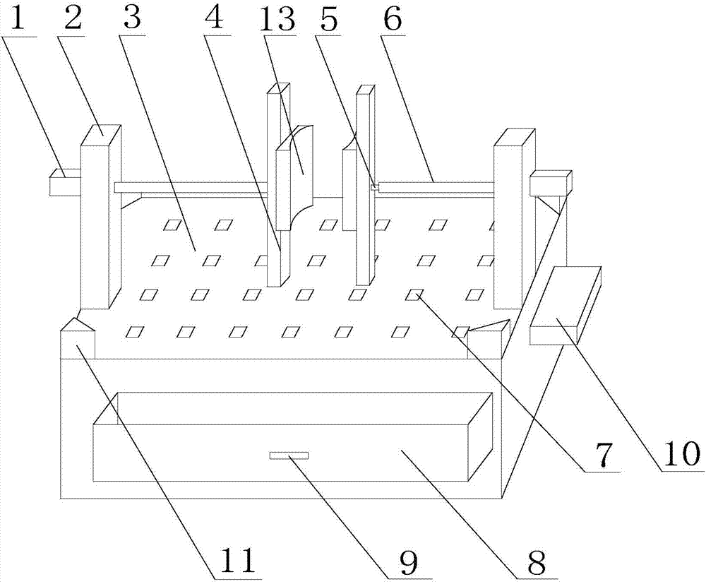
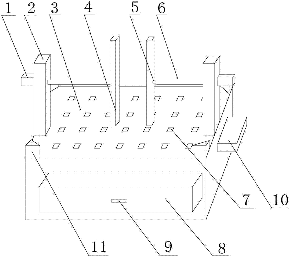
[0028] Such as Figure 1 to Figure 5 As shown, the present invention is applicable to clamping mechanisms for clamping planes or curved surfaces, including a workbench 3 in a rectangular shape, and two support columns 2 are arranged on the top of the workbench 3, and the two support columns 2 are respectively located on the axis of the workbench 3 Both sides, support column 2 is rectangular parallelepiped shape, and length is 60cm, is provided with driving mechanism 1 on the side wall of support column 2, and driving mechanism 1 comprises drive shaft, and drive mechanism 1 is preferably a hydraulic cylinder, and drive shaft is a hydraulic cylinder. The piston rod, the drive shaft crosses on the support column 2, and the end of the drive shaft is provided with a connecting rod 6. Under the action of the driving mechanism 1, the drive shaft can drive the connecting rod 6 to move in the horizontal direction, and one end of the connecting rod 6 Connected with the drive shaft, the ...


PUM


Abstract

The invention discloses a clamping mechanism suitable for clamping a flat surface or a curved surface. The clamping mechanism comprises a workbench, wherein two support columns are arranged at the top of the workbench and a plurality of leakage holes are formed in the top of the workbench; a drive mechanism is arranged on the support columns; a drive shaft of the drive mechanism is inserted into the support columns in a penetrating manner; a connection rod is arranged at the tail ends of the support columns; one end of the connection rod is connected with the drive shaft, and a movable shaft is arranged at the other end of the connection rod; a first clamping block is arranged on the movable shaft; a thread hole is formed in the first clamping block; a screw is arranged in the thread hole; a second fixing block is arranged on the screw; fixing blocks are arranged at the four corners of the top of the workbench; an air blowing pipe is arranged on each fixing block; an air blower and a drawer are further arranged on the side surface of the workbench; the drawer is manufactured from a magnetic material, and the inside of the drawer communicates with the leakage holes; and the air blower is connected with the air blowing pipes. The clamping mechanism disclosed by the invention is capable of fixing a workpiece with the flat surface or the curved surface, and capable of uniformly recovering and storing the chippings generated during a machining process, thereby preventing the chippings from scratching operating personnel.

Description

technical field [0001] The invention relates to the field of workpiece processing devices, in particular to a clamping mechanism suitable for clamping plane or curved surfaces. Background technique [0002] Fixture is a commonly used tool in the process of machining. It is a device used to fix the processing object in the process of mechanical manufacturing so that it can occupy the correct position for construction or inspection. It is used to fix the material or part to be processed, to ensure that it will not move and shift during the processing, and to avoid the deviation of the object to be processed from affecting the precision and accuracy of the processing operation. In a broad sense, in any process of the processing process, the device used to quickly, conveniently and safely install the workpiece can be called a fixture, such as welding fixtures, inspection fixtures, assembly fixtures, machine tool fixtures, etc. Existing fixtures, except some special fixtures spe...

Claims


Application Information

Patent Timeline
Patent Type & Authority Applications(China)
IPC IPC(8): B23Q3/06B23Q11/00
CPCB23Q3/06B23Q3/062B23Q11/00B23Q11/005
Inventor 马赟
Owner LUZHOU YUANCHENG ENG MACHINERY CO LTD
Why Eureka
Try Eureka