Composite nanoimprint lithography machine and working method thereof

A working method and lithography machine technology, applied in nanotechnology, optomechanical equipment, optics, etc., can solve problems such as poor imprinting quality and precision, poor imprinting quality, and low imprinting accuracy, so as to improve accuracy and quality , Simple structure and process, uniform imprinting force

Active Publication Date: 2017-07-04
QINGDAO TECHNOLOGICAL UNIVERSITY
View PDF6 Cites 11 Cited by
  • Summary
  • Abstract
  • Description
  • Claims
  • Application Information

AI Technical Summary

Problems solved by technology

The problems of this method are: on the one hand, the film soft mold will be deformed under the imprinting force during the imprinting process, and direct curing will cause large deformation of the embossed pattern after curing, resulting in low imprinting accuracy and poor imprinting quality. Poor; on the other hand, imprinting and curing are carried out at the same time, requiring imprinting materials to have fast curing performance (which limits the choice of imprinting materials), and at the same time, there is a problem of incomplete curing (even at a very low pressure (2) The embossing force is directly applied to the roller (or the roller shaft). On the one hand, it is difficult to ensure uniform imprinting force, resulting in poor consistency of embossed graphics, and the embossed area is affected. On the other hand, it has poor adaptability to the unevenness of the substrate, especially it is difficult to imprint super-large substrates and fragile substrates; (3) the rotation of the roller drives the connected trachea to rotate, resulting in entanglement of the trachea, The normal and reliable working cycle cannot be realized, especially when the imprinting efficiency is high (the roller rotates very fast), which will cause the equipment to fail to work; (4) The long grooves se

Method used

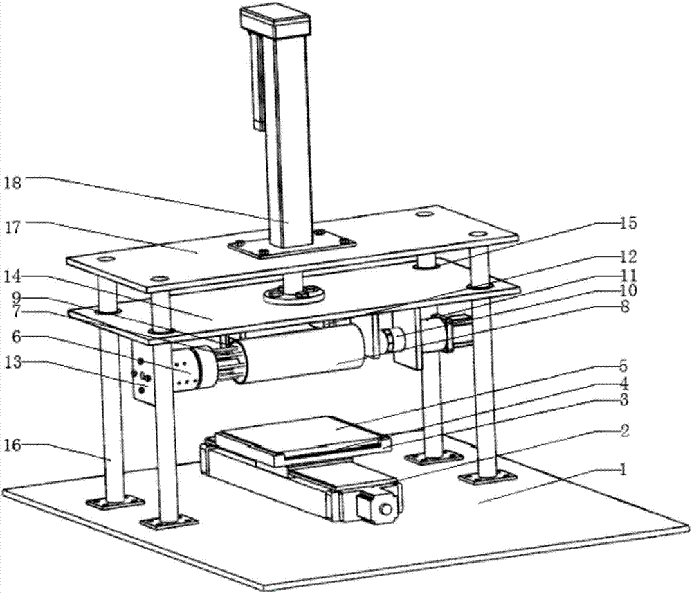
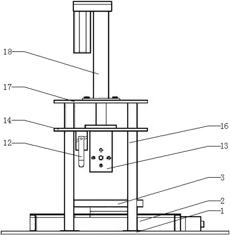
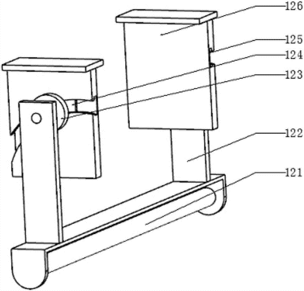

Image

  • Composite nanoimprint lithography machine and working method thereof
  • Composite nanoimprint lithography machine and working method thereof
  • Composite nanoimprint lithography machine and working method thereof

Examples


Embodiment Construction

[0073] It should be pointed out that the following detailed description is exemplary and intended to provide further explanation to the present application. Unless defined otherwise, all technical and scientific terms used herein have the same meaning as commonly understood by one of ordinary skill in the art to which this application belongs.

[0074] It should be noted that the terminology used here is only for describing specific implementations, and is not intended to limit the exemplary implementations according to the present application. As used herein, unless the context clearly dictates otherwise, the singular is intended to include the plural, and it should also be understood that when the terms "comprising" and / or "comprising" are used in this specification, they mean There are features, steps, operations, means, components and / or combinations thereof.

[0075] As introduced in the background technology, the prior art has the disadvantages of low imprint accuracy a...


PUM

PropertyMeasurementUnit
Thicknessaaaaaaaaaa
Thicknessaaaaaaaaaa

Abstract

The invention discloses a composite nanoimprint lithography machine and a working method thereof. By the composite nanoimprint lithography machine, the problems of relatively large deformation, low imprint accuracy and poor imprint quality of an imprint pattern are solved. By closely matching of a roller, a composite soft die and a workbench, large-area imprint and opened demoulding are high-efficiency and automatically completed under joint and synergistic effects of positive pressure and negative pressure, and large-area micronano patterning of an over-sized rigid substrate is achieved. In the technical scheme, the composite nanoimprint lithography machine comprises a base, wherein the workbench is fixed on the base, a vacuum suction disc is arranged on a mobile table surface of the workbench and is attached onto a substrate in a vacuum way, an imprint material is uniformly coated on the substrate, an imprint module is correspondingly arranged on the substrate in a matching way and comprises an imprint assembly and a curing assembly, the imprint assembly comprises the roller, the composite soft die is attached onto an outer surface of the roller in a vacuum way, an elastic material layer wraps the outer surface of the roller, the composite soft die is provided with a flexible material layer, and the flexible material layer is in contact with the roller and is arranged at one side.

Description

technical field [0001] The invention belongs to the technical field of micro-nano manufacturing, and relates to a composite nano-imprint photolithography machine, in particular to a large-area composite nano-imprint photolithography machine and a working method based on roller assistance and a composite soft mold. Background technique [0002] In order to improve and improve the performance and quality of products in the fields of high-definition flat panel display, high-efficiency solar panels, anti-reflection and self-cleaning glass, LED patterning, and wafer-level micro-nano optical devices, there is a huge need for large-area micro-nano patterning technology. industry needs. The common feature of these products is that large-area complex three-dimensional micro-nano structures need to be manufactured efficiently and at low cost on large-scale non-flat rigid substrates (hard substrates or substrates). However, various existing micro-nano manufacturing technologies (such ...

Claims


Application Information

Patent Timeline
IPC IPC(8): G03F7/00B82Y40/00
CPCB82Y40/00G03F7/0002
Inventor 兰红波郭良乐
Owner QINGDAO TECHNOLOGICAL UNIVERSITY
Why Eureka
Try Eureka