
Vector tension device and vector tension control method for vertical take-off and landing unmanned aerial vehicle

A tension device and vertical take-off and landing technology, which is applied in the direction of vertical take-off and landing aircraft, power device on the aircraft, power device arrangement/installation, etc.

Pending Publication Date: 2017-07-07
HEBEI UNIV OF TECH +1
View PDF0 Cites 5 Cited by
  • Summary
  • Abstract
  • Description
  • Claims
  • Application Information

AI Technical Summary

Problems solved by technology

This method requires the UAV to perform a short-distance gliding without reaching the purpose of vertical landing

Method used


Image

  • Vector tension device and vector tension control method for vertical take-off and landing unmanned aerial vehicle
  • Vector tension device and vector tension control method for vertical take-off and landing unmanned aerial vehicle
  • Vector tension device and vector tension control method for vertical take-off and landing unmanned aerial vehicle

Examples


Embodiment Construction

[0018] The present invention will be further described below in conjunction with the accompanying drawings and specific embodiments.

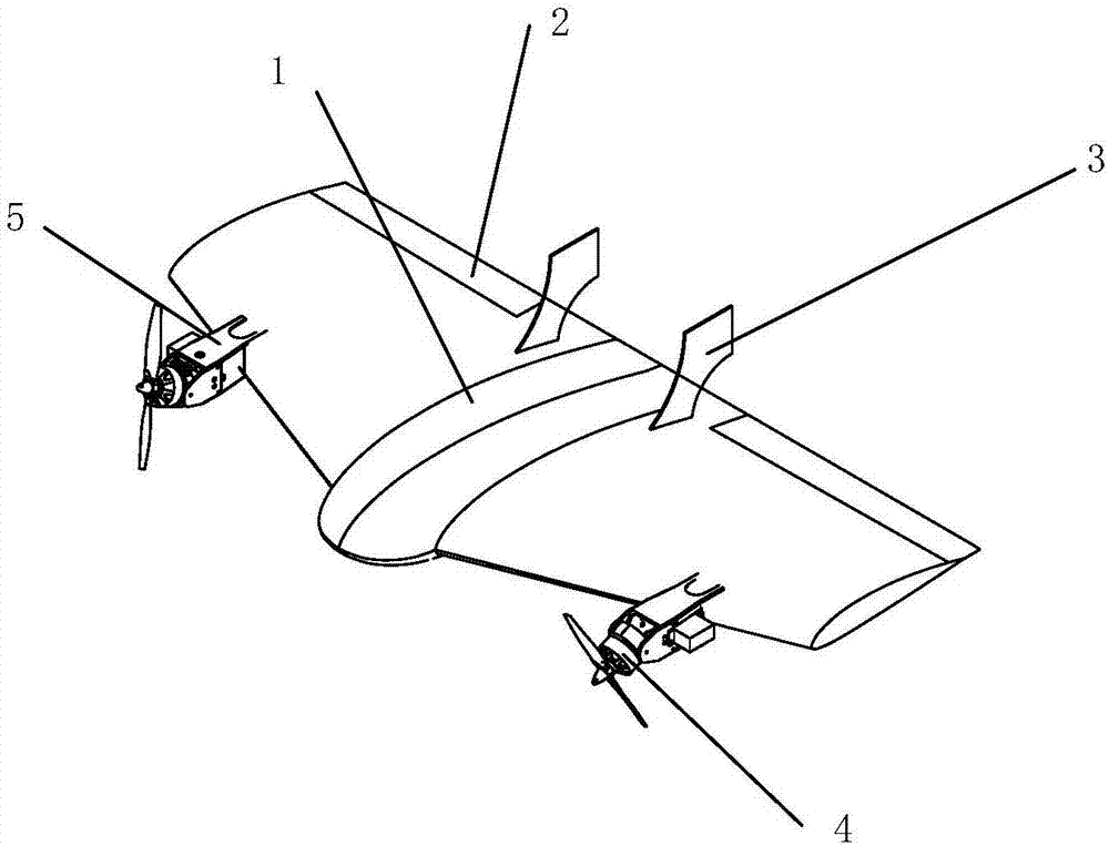
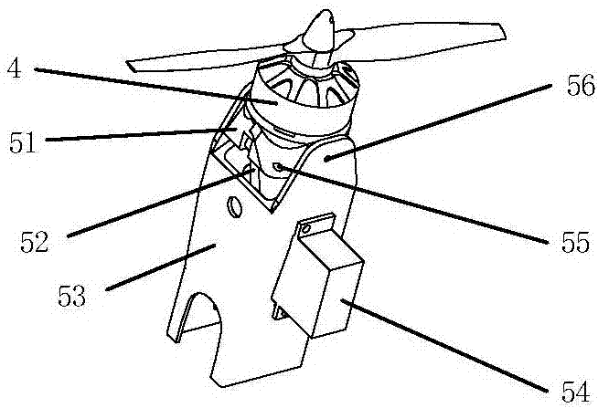
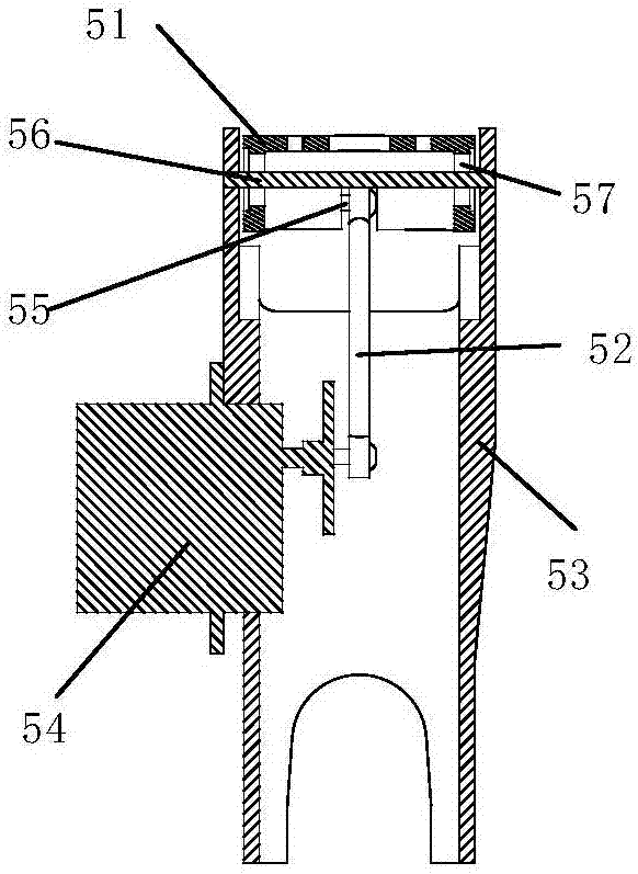
[0019] like Figure 1-4 As shown, the vertical take-off and landing UAV vector tension device, the vertical take-off and landing UAV is provided with a body 1, an aileron 2, a vertical tail 3, an engine 4, and a vector tension device 5. The vertical take-off and landing UAV vector tension device includes a swinging engine mount 51, a ball head tie rod 52, a fixed engine mount 53, a control steering gear 54, a ball head connected to an optical axis 55, and a support connected to an optical axis 56. Blue bearing 57, ball joint 58.

[0020] see Figure 1-4 , the fixed engine mount 53 is fixed on the leading edge of the wing of the body 1 through a mechanical connection, the control steering gear 54 is fixed on the fixed engine mount 53 by four screws, and the engine 4 is fixed on the swinging engine mount 51 by bolts Above, the oscillating engi...


PUM


Abstract

The invention relates to a vector tension device which comprises a swing type engine seat 51, a fixed type engine seat 53, a supporting seat connection optical shaft 56, flange bearings 57, a control steering gear 54, a ball head connecting smooth shaft 55, a ball head pulling rod 52, a first ball head 59 and a second ball head 58. The control steering gear 54 is fixed on the fixed type engine seat 53; the supporting seat connection smooth shaft 56 is connected on the fixed type engine seat 53 through the flange bearings 57; the swing type engine seat 51 is arranged on the supporting seat connection smooth shaft 56; the first ball head 59 is fixed on the side edge of the swing type engine seat 51 through the ball head connecting smooth shaft 55; the second ball head 58 is fixed on a steering gear rocker arm of the control steering gear 54; and the two ball heads are in rigid connection through the ball head pulling rod 52. The invention provides a vector tension control method for the vertical take-off and landing unmanned aerial vehicle through the vector tension device.

Description

technical field [0001] The invention relates to a vertical take-off and landing unmanned aerial vehicle, in particular to a vertical take-off and landing unmanned aerial vehicle vector tension device and a control method thereof. Background technique [0002] The vertical take-off and landing fixed-wing UAV not only has the advantages of long flight time, large task load, and high efficiency of the traditional fixed-wing UAV, but also has the advantages of vertical take-off and landing, hovering, and control of the take-off and landing site of the traditional rotary-wing UAV. Ask for low-level advantages. [0003] Tail-sit vertical take-off and landing UAV is a relatively common vertical take-off and landing UAV. The UAV adopts tail-sit parking, takes off vertically, and gradually tilts from a vertical attitude after reaching a predetermined height, and finally reaches a level flight attitude. . When landing, first climb at a large elevation angle, reduce the engine speed ...

Claims


Application Information

Patent Timeline
IPC IPC(8): B64C29/02B64C27/28B64D27/26
CPCB64C27/28B64C29/02B64U30/20B64U50/14B64U70/00B64D27/40
Inventor 段萍高雪丁承君尹李亮
Owner HEBEI UNIV OF TECH
Features
  • Generate Ideas
  • Intellectual Property
  • Life Sciences
  • Materials
  • Tech Scout
  • Unparalleled Data Quality
  • Higher Quality Content
  • 60% Fewer Hallucinations
Learn More