Hydraulic energy conversion device for blade-free wind machine

An energy conversion device, wind turbine technology, applied in wind turbines, wind energy power generation, engine functions, etc., can solve the problems of noise and visual pollution, impact on the ecological environment, and high installation costs, and achieve the effect of no noise pollution.

Active Publication Date: 2017-07-07
XIANGTAN UNIV
View PDF5 Cites 6 Cited by
  • Summary
  • Abstract
  • Description
  • Claims
  • Application Information

AI Technical Summary

Problems solved by technology

However, it has the disadvantages of noise and visual pollution, high land occupation, impact on the ecological environment, and high installation cost.

Method used


Image

  • Hydraulic energy conversion device for blade-free wind machine
  • Hydraulic energy conversion device for blade-free wind machine
  • Hydraulic energy conversion device for blade-free wind machine

Examples


Embodiment 1

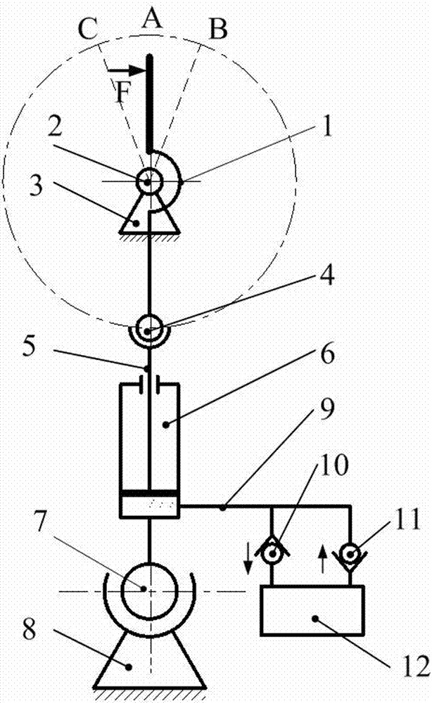
[0023] Embodiment 1, the present invention mainly includes a wind power tower 1, a spherical hinge I2, an upper base 3, a ball joint 4, a piston assembly 5, a cylinder 6, a spherical hinge II7, a lower base 8, a one-way valve I10 and a one-way Valve II11, hydraulic pipe 9 and hydraulic motor 12; the wind tower 1 is fixed on the upper machine base 3 through the spherical hinge I2, the wind tower 1 is connected with the piston assembly 5 through the ball joint 4, and the piston assembly 5 is arranged in the cylinder body 6 , when the wind tower 1 deflects and swings, it drives the piston assembly 5 to move up and down in the cylinder body 6, so that the liquid in the cylinder body 6 is sucked and discharged; the cylinder body 6 is fixed on the lower machine base 8 through the spherical hinge II7, hydraulic One end of the pipe 9 is connected to the cylinder body 6, and the other end is divided into two branches, which are respectively connected to the hydraulic motor through the c...

Embodiment 2

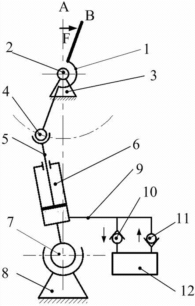
[0024]Embodiment 2, the wind tower 1 is fixed on the upper frame 3 through the spherical hinge I2, and the wind tower 1 can only deflect around the upper frame 3 and cannot rotate around the longitudinal axis of the wind tower 1 itself, thereby preventing the The rotation of the wind tower 1 results in loss of wind energy acquisition. The use of spherical hinge I2 to fix the wind tower 1 on the upper support 3 can ensure that the direction of the wind force received by the wind tower 1 is not limited, and any wind force in the same direction can cause the wind tower 1 to deflect at the same angle and output the same output. rotational kinetic energy. The spherical hinge I2 is used to fix the wind tower 1 on the upper support 3, so that the installation of the bladeless wind turbine is not restricted by the incoming flow direction. refer to Figure 1 to Figure 3 , all the other are with embodiment 1.

Embodiment 3

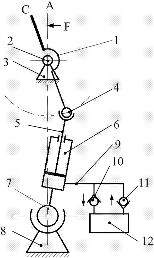
[0025] In Embodiment 3, the wind tower 1 is directly connected to the piston assembly 5 through the ball joint 4, wherein the piston assembly 5 can only deflect around the ball joint 4, but cannot rotate around the longitudinal axis of the piston assembly 5 itself. On the one hand, it can prevent the piston assembly from The assembly 5 itself rotates to cause increased wear and energy loss; on the other hand, when the wind tower 1 deflects in a certain direction under the action of wind, it can ensure that the piston assembly 5 is correspondingly deflected in the opposite direction to the deflection of the wind tower 1. refer to Figure 1 to Figure 3 , and the rest are the same as the above-mentioned embodiment.


PUM


Abstract

The invention relates to a hydraulic energy conversion device for a blade-free wind machine, and mainly solves the technical problems of influence caused by the reason that an existing wind driven generator uses blades and the like. According to the technical scheme, a wind tower (1) is fixed on an upper seat (3) through a spherical hinge I (2), and is connected with a piston assembly (5) through a ball hinge (4); the piston assembly (5) is arranged in a cylinder (6); the cylinder (6) is fixed on a lower seat (8) through a spherical hinge II (7); one end of a hydraulic tube (9) is connected to the cylinder (6); and the other end of the hydraulic tube (9) is divided into two branches which are connected with a hydraulic motor through a one-way valve I (10) and a one-way valve II (11) respectively. The hydraulic energy conversion device for the blade-free wind machine has the advantages of compact structure, convenience in maintenance, low manufacturing cost, zero noise, gearless driving, high energy conversion rate and the like. The received frequency can be doubled.

Description

technical field [0001] The invention belongs to the technical field of wind power generation, in particular to a hydraulic energy conversion device for a bladeless wind turbine. Background technique [0002] As a renewable and non-polluting energy, wind energy has been highly valued by countries all over the world. The use of wind energy for power generation is the main way of wind energy utilization at present. [0003] The basic principle of a bladed wind turbine is that the wind acts on the blades of the wind rotor, thereby driving the wind rotor to rotate, and then increasing the rotation speed through the speed increaser, and then driving the generator to generate electricity. Bladed wind turbines are mainly composed of blades, hubs, speed increasers, generators, iron towers, and tail rudders. They are further divided into horizontal-axis wind turbines and vertical-axis wind turbines. However, it has the disadvantages of noise and visual pollution, high land occupatio...

Claims


Application Information

Patent Timeline
Patent Type & Authority Applications(China)
IPC IPC(8): F03D5/06F03D15/00
CPCF03D5/06F05B2260/406Y02E10/70Y02P70/50Y02E10/72
Inventor 龚曙光王晓雅谢桂兰张建平何聂
Owner XIANGTAN UNIV
Why Eureka
Try Eureka