Eureka AIR delivers breakthrough ideas for toughest innovation challenges, trusted by R&D personnel around the world.

High-temperature-resistant three-eccentric center butterfly valve

A triple eccentric butterfly valve, high temperature resistant technology, applied in the direction of valve lift, valve details, valve device, etc., can solve the problems affecting the sealing and normal use of the butterfly valve, poor high temperature resistance performance of the butterfly valve, uneven force on the valve body, etc. The force is uniform, the opening and closing torque is small, and the effect of reducing sticking

Inactive Publication Date: 2017-07-07
JIANGSU ZHONGHAO MARINE VALVE MFG
View PDF5 Cites 0 Cited by
  • Summary
  • Abstract
  • Description
  • Claims
  • Application Information

AI Technical Summary

Problems solved by technology

This structure can effectively prevent the overflow of the liquid passing through the butterfly valve, but there are obvious defects: because the O-shaped sealing ring is generally a rubber ring, the high temperature resistance is poor, so that the high temperature resistance of the butterfly valve in the prior art is poor; on the other hand , the existing butterfly valve valve plate and valve stem are supported on the end cover at the lower part of the valve body. Since the end cover is fixedly connected to the lower part of the valve body, most of the weight of the valve plate and valve stem acts on the lower part of the valve body, causing the valve body to be affected. Uneven force affects the sealing and normal use of the butterfly valve

Method used


Image

  • High-temperature-resistant three-eccentric center butterfly valve
  • High-temperature-resistant three-eccentric center butterfly valve

Examples


Embodiment Construction

[0019] The present invention will be further described below according to the accompanying drawings and in conjunction with the embodiments.

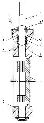
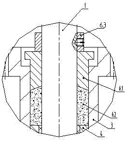
[0020] The high temperature resistant triple eccentric butterfly valve shown in the accompanying drawings includes a valve stem 1, a valve plate 2 and a valve body 3, and the valve stem 1 and valve plate 2 are connected by a spline structure. The valve rod 1 is respectively supported on the upper part and the lower part of the valve body 3 through the upper bearing 4 and the lower bearing 5 arranged up and down. The upper bearing 4 and the lower bearing 5 are composite sliding bearings, which are composed of an outer bush and an inner bush. The outer bush is made of carbon steel, alloy steel or cast iron, and the inner bush is made of friction-resistant, high-temperature-resistant, Made of alloy material with low coefficient of friction, the outer wall of the inner bush is provided with an annular protrusion embedded in the ring groove ...


PUM


Abstract

The invention discloses a high-temperature-resistant three-eccentric center butterfly valve which comprises valve rods, a valve plate and a valve body. The valve rods are supported on the upper portion and the lower portion of the valve body through an upper bearing and a lower bearing which are vertically arranged. A shaft seal structure is arranged at the joint between the upper portion of the valve body and the corresponding valve rod, wherein the shaft seal structure comprises a pressing sleeve, graphite packing and a pressing ring, the valve rod is sleeved with the pressing sleeve front top to bottom, the graphite packing is sealed in an annular groove at the joint between the upper portion of the valve body on the upper portion of the upper bearing and the valve rod, and the pressing ring is installed on the upper end face of the pressing sleeve and fixedly connected with the valve rod. According to the further improvement, the end face, making contact with the graphite packing, of the pressing sleeve is a conical face, and the large end of the conical face is downward; the valve rods and the valve plate are connected through spline structures; and the both the upper bearing and the lower bearing are composite sliding bearings. The high-temperature-resistant three-eccentric center butterfly valve is resistant to high temperature and small in closed torque when in work, the valve body is uniform in stress, sealing is reliable, and maintenance is avoided.

Description

technical field [0001] The invention relates to a valve, in particular to a double eccentric butterfly valve. Background technique [0002] The butterfly valve in the prior art is provided with a shaft seal structure at the upper end of the valve body and the valve stem. The shaft seal structure in the prior art is that a radial shaft seal structure is provided between the upper and lower parts of the valve body and the valve stem, and O-rings and valve seals are embedded in the upper and lower concave ring grooves of the radial shaft seal structure. Rod seal fit. This structure can effectively prevent the overflow of the liquid passing through the butterfly valve, but there are obvious defects: because the O-shaped sealing ring is generally a rubber ring, the high temperature resistance is poor, so that the high temperature resistance of the butterfly valve in the prior art is poor; on the other hand , the existing butterfly valve valve plate and valve stem are supported ...

Claims


Application Information

Patent Timeline
IPC IPC(8): F16K1/22F16K1/226F16K41/04
CPCF16K1/22F16K1/226F16K41/04
Inventor 全文章李顺明
Owner JIANGSU ZHONGHAO MARINE VALVE MFG
Why Eureka
Eureka Blog
Learn More