
Self-balance-weight faucet handle and production technology thereof

A handle and faucet technology, which is applied in the field of self-balancing faucet handle and its production technology, can solve the problems of low overall structural strength, complex manufacturing process, short service life, etc., achieve simple structure, simple manufacturing process, and meet mass production Processing effect

Pending Publication Date: 2017-07-07
王煌源
View PDF6 Cites 2 Cited by
  • Summary
  • Abstract
  • Description
  • Claims
  • Application Information

AI Technical Summary

Problems solved by technology

However, after one-time injection molding of the existing plastic faucet, the overall handle is light in weight and poor in texture, and it is prone to breakage with the prolongation of use time, and the service life is short
In addition, a small part of the existing technology is designed to add a counterweight in the handle, but its manufacturing process is relatively complicated, and the overall structural strength is low

Method used


Image

  • Self-balance-weight faucet handle and production technology thereof
  • Self-balance-weight faucet handle and production technology thereof

Examples


Embodiment 1

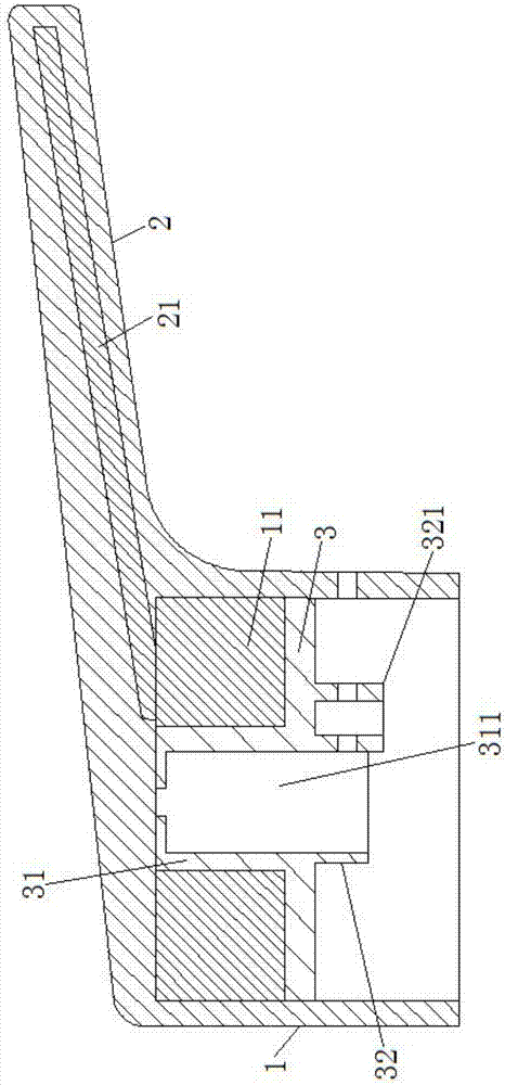
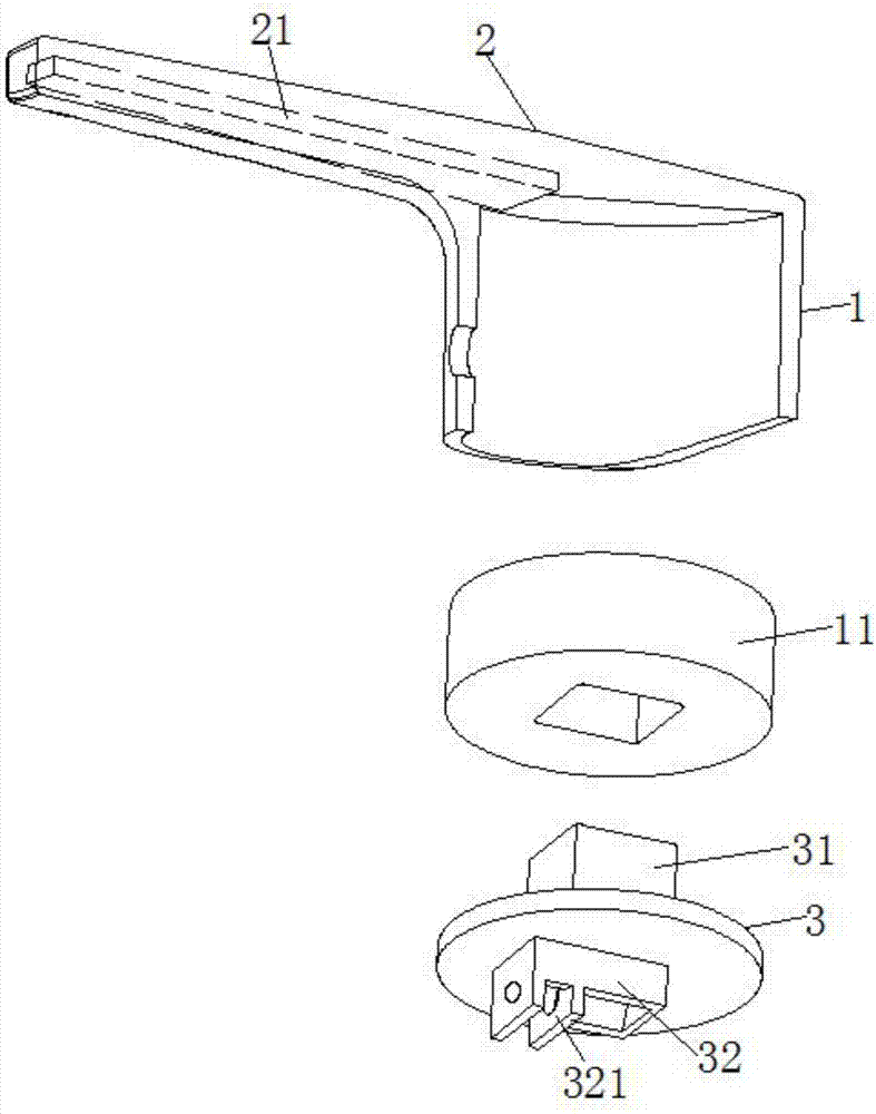
[0035] Embodiment one: if figure 1 and 2 As shown, the self-balancing faucet handle of this embodiment includes a handle body 1, a handle 2, and a cover 3;

[0036] The above-mentioned handle 2 is integrally formed on the above-mentioned handle body 1, the above-mentioned handle body 1 is a cylindrical structure with an open lower end, a first counterweight 11 is arranged in the above-mentioned handle body 1 close to the closed end, and the above-mentioned cover 3 is arranged on On the inner wall of the above-mentioned handle body 1, and press the above-mentioned first counterweight 11 on the closed end of the above-mentioned handle body 1;

[0037] The upper end of the cover 3 is provided with a positioning block 31, and the above-mentioned first counterweight 11 is provided with a positioning hole passing through it up and down and corresponding to the above-mentioned positioning block 31, and the above-mentioned positioning block 31 extends into the above-mentioned positio...

Embodiment 2

[0046] Embodiment 2: A kind of production process of the self-balancing faucet handle as described above in Embodiment 1, comprising the following steps:

[0047] Step 1: Weld and fix the first counterweight 11 and the second counterweight 21, and ensure that one end of the second counterweight 21 is welded to the top side of the first counterweight 11;

[0048] Step 2: Insert the cover 3 into the above-mentioned positioning hole through the positioning block 31 at the upper end, insert the nut into the above-mentioned nut installation groove 321, and place the entire first counterweight 11, the second counterweight 21 and the sealing The cover 3 is put into the mold upside down;

[0049] Step 3: Integral injection molding, specifically, injection molding liquid is injected into the mold through the injection molding channel at the connecting portion 32 of the valve stem, and the faucet handle is formed by integral injection molding.

[0050] The process is simple to manufact...


PUM


Abstract

The invention relates to a faucet fitting, in particular to a self-balance-weight faucet handle and a production technology thereof. The self-balance-weight faucet handle disclosed by the invention comprises a handle body, a hand shank and a closing cap, wherein the hand shank is arranged on the handle body in an integrally molded manner; the handle body is in a cylindrical structure, wherein an opening is formed in the lower end of the handle body; a first balance weight is arranged in the handle body, and abutted against a closing end; the closing cap is arranged on the inner wall of the handle body, and compresses the first balance weight at the closing end in the handle body; a positioning block is arranged at the upper end of the closing cap; a positioning hole which vertically penetrates through the first balance weight and corresponds to the positioning block is formed in the first balance weight; the positioning block extends into the positioning hole; a valve rod connection part is arranged at the lower end of the closing cap; a valve rod is connected with the valve rod connection part; and a second balance weight is arranged in the hand shank. The self-balance-weight faucet handle has the advantages of being simple in structure, high in structural stability, simple in manufacturing technology, low in cost, good in hand feeling, and not liable to break off.

Description

technical field [0001] The invention relates to a faucet fitting, in particular to a self-weighting faucet handle and a production process thereof. Background technique [0002] Plastic faucets are generally made of PVC, ABS, PP and other materials through mass production of molds. Compared with other materials, plastic faucets are light in weight, free of dirt, odorless, rust-free, cheap, and easy to construct. They are widely used in in various areas of life. However, after one-time injection molding of the existing plastic faucet, the overall handle is light in weight and poor in texture, and it is prone to breakage with the prolongation of use time, and the service life is short. In addition, a small part of the existing technology is designed to add a counterweight in the handle, but the manufacturing process is relatively complicated and the overall structural strength is low. Contents of the invention [0003] The technical problem to be solved by the present inve...

Claims


Application Information

Patent Timeline
IPC IPC(8): F16K31/60
CPCF16K31/60Y02A20/411
Inventor 王煌源
Owner 王煌源
Learn More