Indoor simulation test device for studying impact of piping on tunnel and grouting control

A simulation device and simulation test technology, applied in measurement devices, instruments, surveying, mapping and navigation, etc., can solve problems such as inaccurate response, inability to consider the interaction between soil and seepage, inability to analyze piping from a mechanism, etc. Good, highly scalable effect

Active Publication Date: 2017-07-07
UNIV OF SHANGHAI FOR SCI & TECH
View PDF4 Cites 2 Cited by
  • Summary
  • Abstract
  • Description
  • Claims
  • Application Information

AI Technical Summary

Problems solved by technology

Theoretical analysis methods mainly come from engineering experience, and the empirical values ​​obtained by statistical methods cannot analyze the cause of piping from the mechanism; the stochastic model only describes a certain factor and process of piping in a macroscopic manner, and cannot fully explain the occurrence of piping. The mechanism of the numerical simulation is limited to the range of finite element simulation of seepage, the seepage is separated from the soil, and the interaction between the soil and the seepage cannot be considered; the method of on-site monitoring is affected by the size effect, boundary conditions and soil conditions , so that the monitoring results cannot accurately reflect the actual working conditions

Method used


Image

  • Indoor simulation test device for studying impact of piping on tunnel and grouting control
  • Indoor simulation test device for studying impact of piping on tunnel and grouting control
  • Indoor simulation test device for studying impact of piping on tunnel and grouting control

Examples


Embodiment Construction

[0016] The present invention will be further described in detail through a preferred example below in conjunction with the accompanying drawings.

[0017] First, make a model box 1, a tunnel lining model 2, a piping simulation device, and a grouting simulation device.

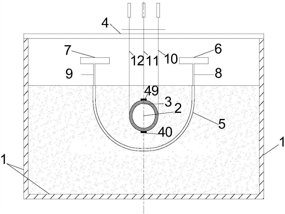
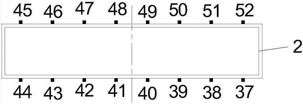
[0018] figure 1 It is a schematic diagram of the simulation test device in the model box in the embodiment of the present invention, as figure 1 As shown, the shape of the model box 1 is a cuboid, and the internal space size is 800 mm × 500 mm × 500 mm (length × width × height), which is composed of five aluminum alloy plates with a thickness of 15 mm. The tunnel lining model 2 is a four-section hollow aluminum alloy tube 3 with an outer diameter of 80 mm, an inner diameter of 70 mm, a wall thickness of 5 mm, and an axial segment length of 100 mm. The lining model segment has an outer diameter of 100 mm and an inner diameter of 70 mm.

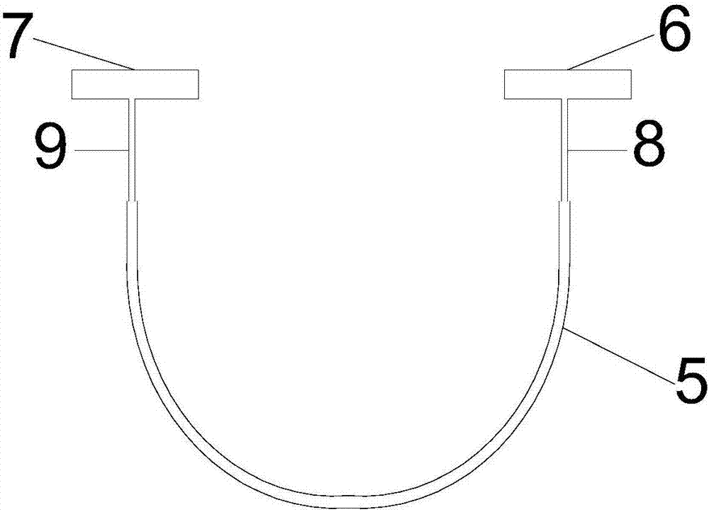
[0019] figure 2 It is a schematic diagram of the piping simulation dev...


PUM


Abstract

The invention relates to an indoor simulation test device for studying impact of piping on a tunnel and grouting control. The indoor simulation test device comprises a model box, a tunnel lining model, a piping simulation device, a grouting simulation device, a plurality of strain gauges, a displacement gauge bracket and a plurality of displacement gauges. The tunnel lining model is of a segmented hollow aluminum tube, the piping simulation device consists of a plastic film filled with sand, and the occurrence of a piping permeation phenomenon is simulated by injecting a certain volume of water solution. The grouting simulation device consists of a grouting pipe and a grouting device which are arranged at the two ends of the piping simulation device, wherein the plurality of strain gauges cling to the outer wall of the tunnel so as to measure the strain of the tunnel; the displacement gauges are fixedly arranged on the displacement gauge bracket so as to measure a soil body at the upper part of a tunnel model and tunnel settlement. The indoor simulation test device provided by the invention aims at studying the impact of a piping phenomenon on the tunnel and grouting control, and is of great reference value for formulating a technical standard of tunnel construction safety crossing and piping phenomenon control.

Description

technical field [0001] The invention relates to a tunnel simulation test device in urban underground space development and underground construction engineering, in particular to an indoor simulation test device for research on the influence of piping on tunnels and grouting treatment. Background technique [0002] With the further development of urbanization in our country, urban underground rail transit, as the most convenient and efficient urban transportation system, has also developed rapidly, and more and more river-crossing tunnels are being constructed. In the process of tunnel construction, leakage and piping accidents often occur due to problems in joint treatment of support structures or improper precipitation. The problem of piping in tunnel construction is very serious, and it has caused very serious losses to many projects. If the cause of the accident cannot be clearly analyzed and effective measures are taken, it will not only fail to ensure the safety of the...

Claims


Application Information

Patent Timeline
IPC IPC(8): G01C5/00G01B21/32
CPCG01B21/32G01C5/00
Inventor 张治国黄茂松师敏之王卫东
Owner UNIV OF SHANGHAI FOR SCI & TECH
Why Eureka
Try Eureka