High-precision large-aperture grating five-degree-of-freedom splicing precision measurement method
A technology of large-diameter grating and measurement method, which is applied in the directions of measurement device, optical instrument test, machine/structural component test, etc. Improve the splicing accuracy and measure the effect of low coupling
- Summary
- Abstract
- Description
- Claims
- Application Information
AI Technical Summary
Problems solved by technology
Method used
Image
Examples
specific Embodiment approach 1
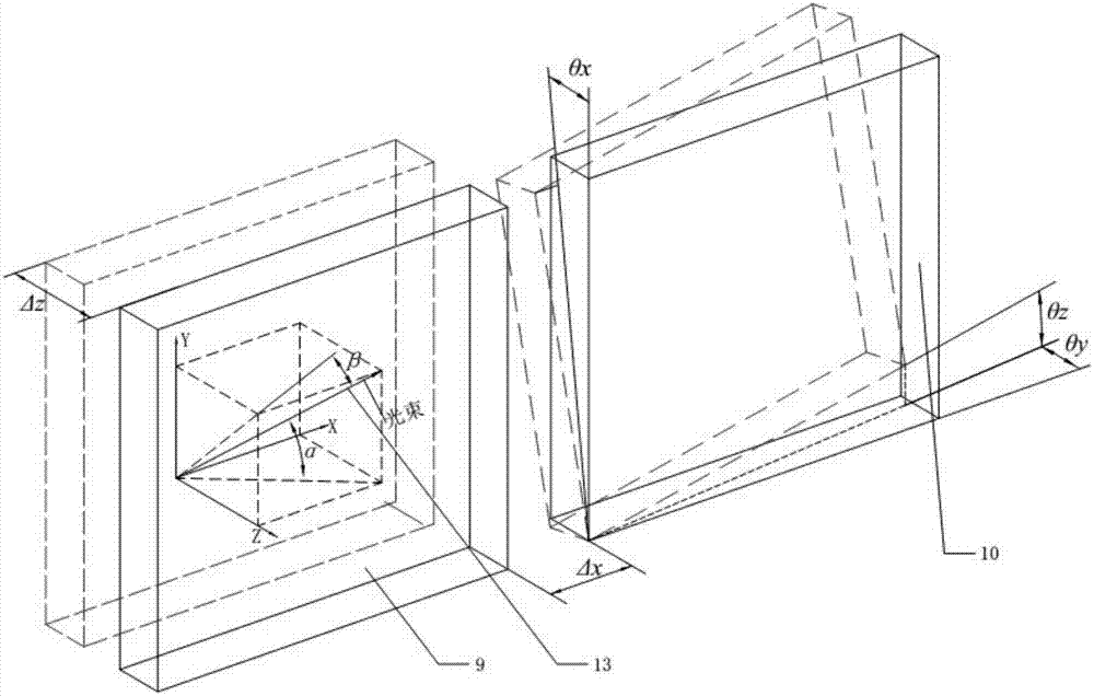
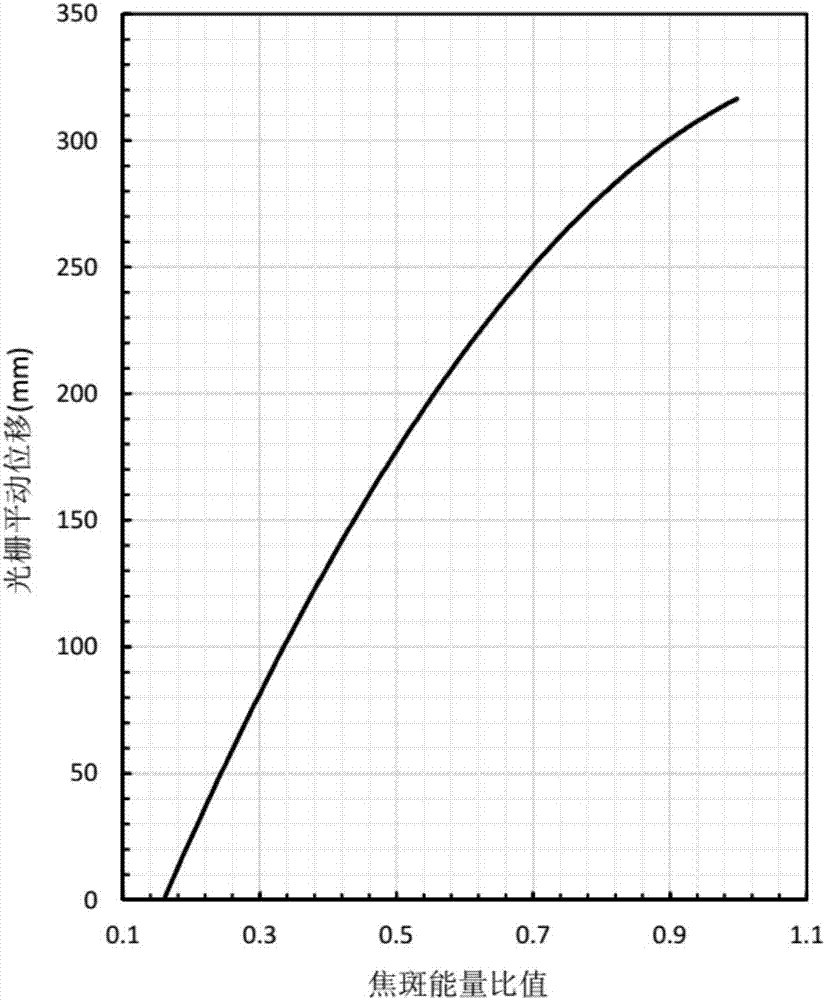
[0032] Specific Embodiment 1: This embodiment provides a method for comprehensively utilizing reflected light and diffracted light to realize splicing accuracy measurement of large-aperture gratings. Based on the principle of light interference, the interference field of the zero-order reflected light and the first-order diffracted light of the grating is used. The pitch, deflection and rotation angles of the grating are measured respectively, and the two-dimensional translational accuracy of the grating is measured by the energy ratio of the split far-field focal spot. Specific steps are as follows:
[0033] 1. Measurement of the three-dimensional rotation accuracy of the grating
[0034] When the incident measuring beam passes through the seam of the spliced grating, the spatial direction of the outgoing beam will be deflected, and the diffracted light generated by the two gratings will be imaged separately in the CCD image sensor, and the deflection angle of the beam can ...
specific Embodiment approach 2
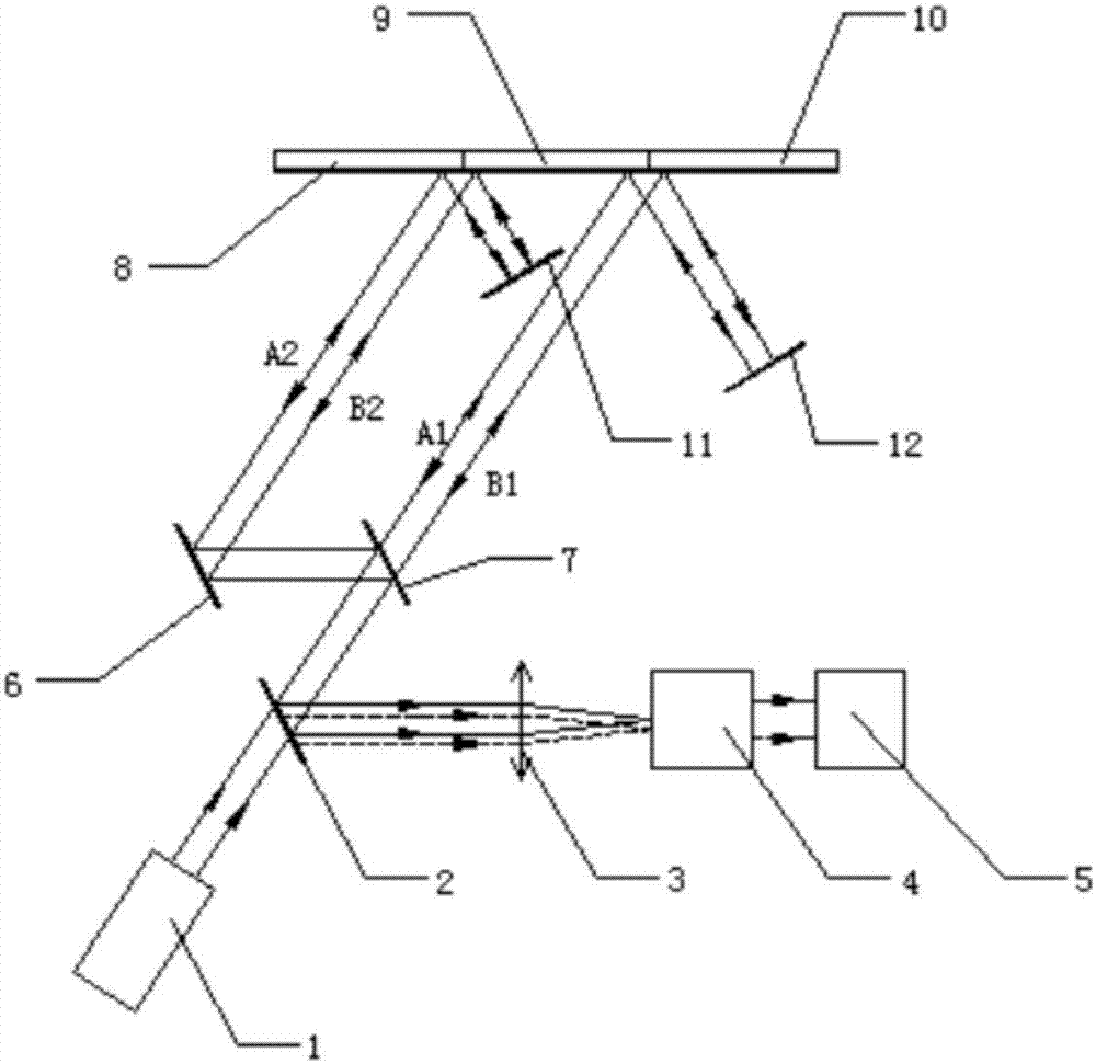
[0064] Specific implementation mode 2: This implementation mode provides a method of comprehensively utilizing reflected light and diffracted light to realize the splicing accuracy measurement of large aperture gratings. In this method, three gratings composed of static gratings in the middle and moving gratings on both sides are spliced. The resulting large-aperture grating group is the object. Such as figure 1 and figure 2 As shown, the specific measurement steps are as follows:
[0065] Measurement step 1: The pitch angle θ of the moving grating B10 relative to the static grating 9 x and deflection angle θ y Measurement.
[0066] Adjust the optical path system so that the measurement sub-beams A1 and B1 emitted by the light source system 1 are transmitted by the half-mirror A2 and then incident on the seam between the static grating 9 and the moving grating B10, and the zero-order beam emitted by the moving grating B10 and the static grating 9 The reflected light retu...
specific Embodiment approach 3
[0071] Specific embodiment three: the difference between this embodiment and specific embodiment two is that the test optical path is switched: in the optical path system, the half mirror B7 and reflector A6 and reflector B11 arranged in parallel are increased in the optical path system, and the positions of other optical devices constant. The specific test steps are as follows:
[0072] Measurement step 1: The pitch angle θ of the moving grating A8 relative to the static grating 9 x and deflection angle θ y Measurement.
[0073] After the measurement sub-beams A1 and B1 emitted by the light source system 1 are transmitted by the half-mirror A2, and then reflected by the half-mirror B7 and the reflector A6 in turn, translation occurs, and the sub-beams after translation are A2 and B2, The sub-beams A2 and B2 are incident on the seam between the moving grating A8 and the static grating 9, and the zero-order reflected light emitted by the moving grating A8 and the static grat...
PUM
 Abstract
Description
Claims
Application Information
 - R&D
- Intellectual Property
- Life Sciences
- Materials
- Tech Scout
- Unparalleled Data Quality
- Higher Quality Content
- 60% Fewer Hallucinations
Browse by: Latest US Patents, China's latest patents, Technical Efficacy Thesaurus, Application Domain, Technology Topic, Popular Technical Reports.
© 2025 PatSnap. All rights reserved.Legal|Privacy policy|Modern Slavery Act Transparency Statement|Sitemap|About US| Contact US: help@patsnap.com


