Organic electroluminescent display device and display device

An electroluminescent display and display device technology, which is applied in the direction of electric solid state devices, electrical components, semiconductor devices, etc., can solve problems such as large stress, affecting the mechanical quality of the device, and affecting the luminous quality of the device

Active Publication Date: 2017-07-07
BOE TECH GRP CO LTD +1
View PDF6 Cites 11 Cited by
  • Summary
  • Abstract
  • Description
  • Claims
  • Application Information

AI Technical Summary

Problems solved by technology

Affect the quality of light emission of the device
In addition, in actual production, the greater the laser energy, the greater the temperature gradient of the glass glue after passing through the packagin

Method used


Image

  • Organic electroluminescent display device and display device
  • Organic electroluminescent display device and display device
  • Organic electroluminescent display device and display device

Examples


Embodiment Construction

[0027] Embodiments of the present invention are described in detail below. The embodiments described below are exemplary only for explaining the present invention and should not be construed as limiting the present invention. If no specific technique or condition is indicated in the examples, it shall be carried out according to the technique or condition described in the literature in this field or according to the product specification. The reagents or instruments used were not indicated by the manufacturer, and they were all commercially available conventional products.

[0028] In one aspect of the invention, the invention provides an organic electroluminescent display device. According to an embodiment of the present invention, refer to Figure 4 , the organic electroluminescent display device includes: a pixel array 10 ; encapsulation glue 20 surrounding the pixel array; a laser reflector 30 for reflecting edge laser light to the encapsulation glue 20 . As a result, t...


PUM


Abstract

The present invention provides an organic electroluminescent display device and a display device. The organic electroluminescent display device comprises a pixel array, a packaging adhesive arranged around the pixel array, and a laser reflection piece used for reflecting the edge laser to the packaging adhesive. In this way, the laser reflection piece reflects the edge laser to the packaging adhesive, wherein the edge laser might burn pixels. As a result, pixels are prevented from being burned, and the utilization rate of the laser is increased at the same time. The energy is efficiently utilized and the energy loss is reduced. Meanwhile, the packaging performance of the glass cement is improved and the temperature gradient of the packaging adhesive can be reduced. The stress generation is avoided. The packaging capability and the mechanical quality of the device are improved.

Description

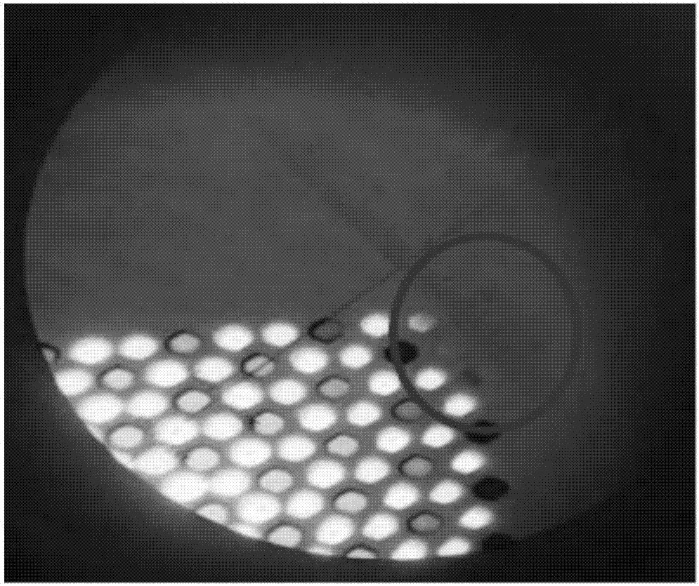
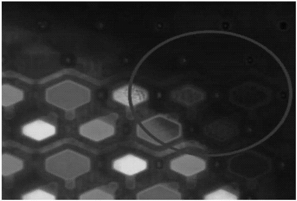
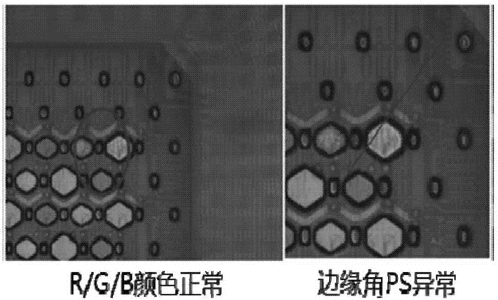
technical field [0001] The invention relates to the field of display, in particular to an organic electroluminescence display device and a display device. Background technique [0002] At present, rigid organic electroluminescent display devices (OLEDs) generally use glass glue as the packaging material, and laser sintering is used for effective packaging. Under the condition of a certain laser moving speed, the energy absorbed by the packaging area is related to the laser energy and the laser trajectory. . [0003] In actual production, the laser is used to irradiate the glass glue packaging area. At the corner of the OLED device, the packaging area is affected by the laser trajectory. The inner corner receives more energy from the laser irradiation than the outer corner, and the pixels here are most likely to be burned. Under lighting, refer to figure 1 , the edge corner pixel (Pixel) emits abnormal light; under the fluorescence microscope, refer to figure 2 , R / G / B ex...

Claims


Application Information

Patent Timeline
IPC IPC(8): H01L51/52H01L27/32
CPCH10K59/00H10K50/84H10K59/352H10K50/856H10K59/12
Inventor 王利娜张亮王浩田王子峰
Owner BOE TECH GRP CO LTD
Why Eureka
Try Eureka