
Wireless channel resource allocation method

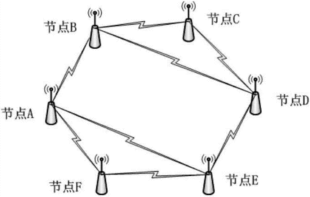
A resource allocation and wireless channel technology, which is applied in transmission path sub-channel allocation, wireless communication, signaling allocation, etc., can solve problems such as increasing negotiation channel conflicts, aggravating negotiation channel load, and increasing communication delay, so as to reduce control Effects of information overhead, reduction of negotiation times, and communication delay

Active Publication Date: 2017-07-07
JIANGSU ZHONGKE YILIAN COMM TECH CO LTD
View PDF4 Cites 5 Cited by
  • Summary
  • Abstract
  • Description
  • Claims
  • Application Information

AI Technical Summary

Problems solved by technology

In this scheme, the data transmission requirements of the wireless communication nodes are dynamically changing. From the source communication node applying for resources to the target communication node replying the confirmation message, the source node may generate new data transmission requirements. In this way, it is necessary to New data transmission needs to apply for resources multiple times, which increases the number of negotiations, increases the load of the negotiation channel for the entire network, and also increases the probability of conflicts on the negotiation channel, which is not conducive to communication nodes for a single communication node power saving, and the new data requirements are not met in time, which increases the communication delay

Method used


Image

  • Wireless channel resource allocation method
  • Wireless channel resource allocation method
  • Wireless channel resource allocation method

Examples


Embodiment 1

[0059] Assuming that node A has 5 symbols of data to be sent to node B at a certain moment, the wireless channel resource allocation method includes the following steps:

[0060] S1: The maximum number of symbols is determined to be 100 by using a static determination method;

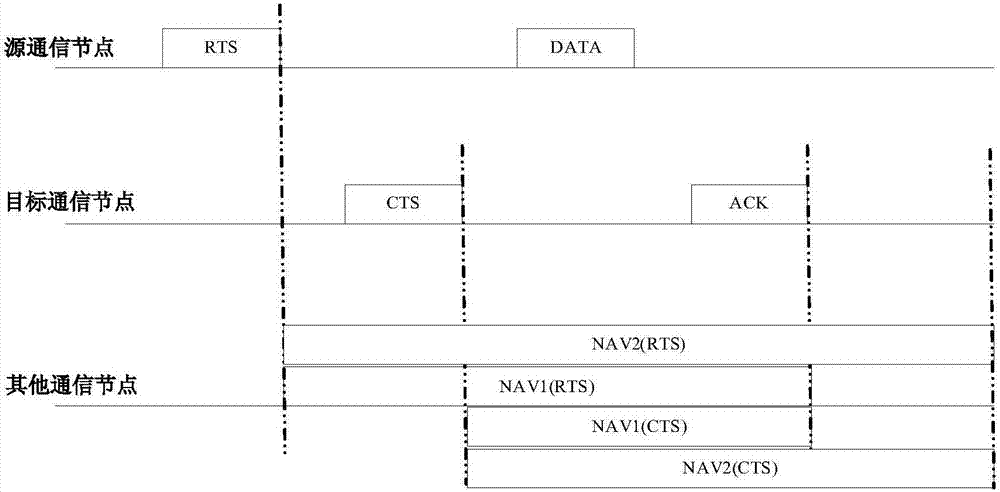
[0061] S2: Before sending data, node A first queries NAV2 information and finds that there are 3 data channels fb, fc, and fd that are free, then randomly selects channel fd as the data channel from these three data channels, and sends it on the negotiated channel obtained through competition The RTS frame is sent to node B, and the RTS frame carries the number of symbols of node A's data to be sent 7, the maximum number of symbols that node A can occupy channel resources of 100, and the data channel fd that node A requires to occupy; the number of symbols of node A's data to be sent 7 includes the transceiving conversion of 1 symbol, the ACK frame of 1 symbol and the data to be sent of 5 symbols;

[0...

Embodiment 2

[0067] Assuming that node A has 5 symbols of data to be sent to node B at a certain moment, the wireless channel resource allocation method includes the following steps:

[0068] S1: Use a dynamic determination method to determine the maximum number of symbols, set Prate=100, Lavg=10 symbols, t=36×10 -6 Second, Lreq=15 symbols are substituted in formula (1), calculate and obtain maximum symbol number Smax to be 40 symbols;

[0069] S2: Before sending data, node A first queries NAV2 information and finds that there are 3 data channels fb, fc, and fd that are free, then randomly selects channel fd as the data channel from these three data channels, and sends it on the negotiated channel obtained through competition The RTS frame is sent to node B, and the RTS frame carries the number of symbols of the data to be sent by node A 7, the maximum number of symbols of the channel resources that node A can occupy is 40, and the data channel fd required by node A; the number of symbols ...


PUM


Abstract

The invention discloses a wireless channel resource allocation method which comprises the four steps of: determining a maximum symbolic number; before sending data, applying for node wireless channel resources; by a target node, confirming the wireless channel resources; and by a source node, sending the data. By the wireless channel resource allocation method, a data sending requirement of a wireless communication node can be timely met, consultation times are reduced, control information cost on a consultation channel is reduced, and a performance bottleneck caused by a case that when a network load is large, the consultation channel has massive control information so as to cause a large collision probability is avoided. When the network load is small, a reaching frequency of a data packet is relatively low, and the wireless channel resource allocation method disclosed by the invention does not cause performance deterioration; when the network load is large, the reaching frequency of the data packet is relatively high; the wireless channel resource allocation method disclosed by the invention can utilize resources allocated for once to the greatest degree, promotes a throughput of a wireless communication network, and reduces total sending times of the communication node so as to reduce power consumption of the communication node and meanwhile, reduce integral communication time delay of the wireless communication network.

Description

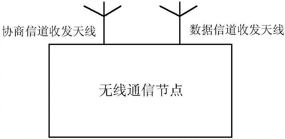
technical field [0001] The invention relates to the field of wireless communication, in particular to a method for allocating wireless channel resources. Background technique [0002] Compared with traditional wireless communication networks, wireless ad hoc networks have the characteristics of fast networking, low requirements for infrastructure, and strong resistance to destruction. They are widely used in military communications, rescue and disaster relief, and intelligent transportation. [0003] Similar to the OSI model of the TCP / IP protocol stack, the underlying protocol stack of the wireless ad hoc network can also be divided into a physical layer (PHY), a medium access control layer (MAC) and a network layer (NET), among which the MAC layer is responsible for access control and wireless resource allocation. The MAC layer protocol will directly affect performance indicators such as network delay, throughput, and channel utilization. Therefore, choosing an appropriat...

Claims


Application Information

Patent Timeline
Patent Type & Authority Applications(China)
IPC IPC(8): H04L5/00H04W28/04H04W72/04
CPCH04L5/0055H04W72/0446H04W74/0841H04W72/52Y02D30/70
Inventor 于建超慕福奇吕欣岩
Owner JIANGSU ZHONGKE YILIAN COMM TECH CO LTD
Learn More