Compound driven shoulder joint

A shoulder joint and driver technology, applied in the field of compound drive shoulder joints, can solve the problems of cumbersome operation, insufficient precision, and high precision of heavy load of the robot arm, and achieve the effect of flexible work and easy realization.

Pending Publication Date: 2017-07-11
CHONGQING JIAOTONG UNIVERSITY
View PDF7 Cites 8 Cited by
  • Summary
  • Abstract
  • Description
  • Claims
  • Application Information

AI Technical Summary

Problems solved by technology

Among them, the motor drive is a relatively traditional driving method, which has large driving displacement, high driving precision, simple driving circuit, low energy consumption, and convenient control, but has the defect of small driving torque; in addition, in order to provide larger torque, the existing There are a variety of joints with compound drive structures, but most of them are complex in structure, cumbersome in operation, low in sensitivity, and in some cases still have the disadvantage of insufficient precision
That is to say, in the existing technology, the drive of the robot arm still has the problem that the heavy load and high precision cannot be guaranteed at the same time. How to solve this technical problem has become an imminent challenge

Method used


Image

  • Compound driven shoulder joint

Examples


Embodiment Construction

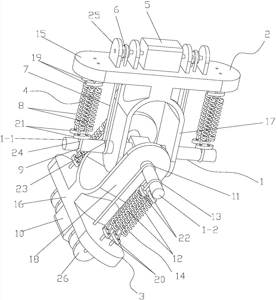
[0018] figure 1 It is a schematic diagram of the overall structure of the present invention, as shown in the figure: the composite drive shoulder joint of this embodiment includes a cross shaft 1, a movable hinge frame 2 and a fixed hinge frame 3, and is respectively used to drive the swing motion and pitch of the movable hinge frame 2 The swing drive part and the pitch drive part of the movement; the movable hinge frame 2 rotates with the first shaft body 1-1 of the cross shaft 1, and the second shaft body 1-2 of the cross shaft 1 rotates with the fixed hinge frame 3; as shown in the figure As shown, the cross shaft 1 is composed of the first shaft body 1-1 and the second shaft body 1-2 connected in a cross shape. The movable hinge frame 2, the fixed hinge frame 3 and the cross shaft 1 together form a Hooke hinge structure. , the fixed hinge frame 3 is fixed, and the movable hinge frame 2 is fixed with the big arm of the robot. The movable hinge frame 2 can produce rotation a...


PUM


Abstract

The invention discloses a compound driven shoulder joint. The compound driven shoulder joint comprises a cross shaft, a movable hinge frame and a fixed hinge frame, and a swing driving part and a pitching driving part for respectively driving the movable hinge frame to swing and pitch; the movable hinge frame is rotationally matched with a first shaft body of the cross shaft; a second shaft body of the cross shaft is rotationally matched with the fixed hinge frame; the swing driving part and the pitching driving part both adopt a memory alloy drive and electric drive combination driving mode; and in a swing driving mode and a pitching driving mode, the precise driving of single motor at low load can be realized, and the heavy-load and high-precision combination driving of memory alloy drive and electric drive synchronous driving at heavy load also can be realized.

Description

technical field [0001] The invention relates to the field of mechanical joints, in particular to a compound-driven shoulder joint. Background technique [0002] With the development of robot technology, people hope that the new robot arm will have high precision, fast response, good quality, long life, low energy consumption, small size, light weight, large torque, strong carrying capacity, high reliability, and intelligence. , modularity, reconfigurability, etc., but also hope to have good flexibility to obtain better security and self-recovery capabilities. There are mainly two drive modes for the drive joints of existing robot arms, one is single drive drive, such as traditional motor drive, hydraulic drive and pneumatic drive, and new memory alloy, piezoelectric ceramics, pneumatic artificial muscles and other drives. Among them, the motor drive is a relatively traditional driving method, which has large driving displacement, high driving precision, simple driving circu...

Claims


Application Information

Patent Timeline
Patent Type & Authority Applications(China)
IPC IPC(8): B25J17/02
CPCB25J17/0266B25J17/0275
Inventor 罗天洪李会兰
Owner CHONGQING JIAOTONG UNIVERSITY
Why Eureka
Try Eureka