Petrol station buried tank cleaning system

A cleaning system and gas station technology, applied in the field of cleaning, can solve the problems of insufficient utilization of oil products, health hazards of operators, waste of sewage sludge, etc., to save cleaning water consumption, reduce cleaning time, and avoid potential safety hazards. Effect

Pending Publication Date: 2017-07-14
成都佳辉蓉达环保科技有限公司
View PDF5 Cites 2 Cited by
  • Summary
  • Abstract
  • Description
  • Claims
  • Application Information

AI Technical Summary

Problems solved by technology

[0004] The invention proposes a cleaning system for buried tanks in gas stations. The problem to be solved is that a large amount of sewage sludge is wasted during the cleaning process of buried tanks in gas stations, the cleaning time is long, and the cleaned oil is not fully utilized, causing environmental pollution. Serious and hazardous to the health of the operator

Method used


Image

  • Petrol station buried tank cleaning system

Examples


Embodiment Construction

[0029] The present invention will be described in further detail below in conjunction with specific embodiments and accompanying drawings.

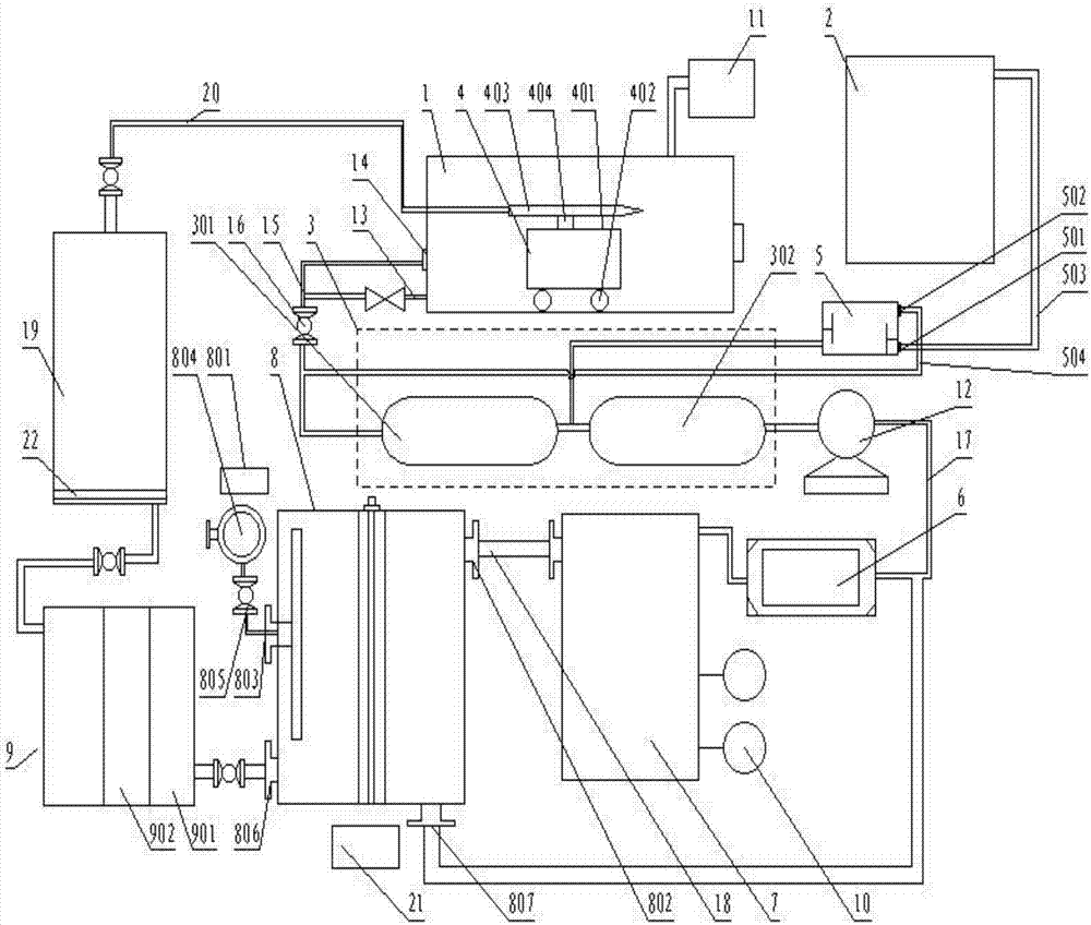
[0030] A gas station buried tank 1 cleaning system such as figure 1 As shown, it includes buried tank 1, cleaning recovery device 3, cleaning machine 4, oil-water separation device 5, sludge dehydrator 6, reaction tank 7, air flotation machine 8, filter device, dosing device 10, inert gas generator 11 and a vacuum pump 12; the buried tank 1 below is provided with a drain valve 13 and an outlet 14, and the drain valve 13 and the outlet 14 are connected to the cleaning recovery device 3 through the recovery pipeline 15; the cleaning recovery device 3 includes a vacuum tank 301 and a recovery tank 302; The vacuum tank 301 is connected to the recovery tank 302, and an oil-water separation device 5 is arranged between the vacuum tank 301 and the recovery tank 302. The oil-water separation device 5 is provided with an oil return outlet 501 and ...


PUM


Abstract

The invention discloses a petrol station buried tank cleaning system. The petrol station buried tank cleaning system comprises a buried tank, a cleaning recycling device, a cleaning machine, an oil-water separation device, a sludge dewatering machine, a reaction tank, an air flotation machine, a filtering device, a cleanser adding device, an inert gas generator and a vacuum pump, wherein the lower portion of the buried tank is provided with a water discharging valve and an outlet which are connected in the cleaning recycling device through recycling pipelines. According to the petrol station buried tank cleaning system, cleaned oil products can be reused, waste of oil products is prevented, and the resource reutilization rate is greatly improved. Sewage is recycled, the whole cleaning system becomes a closed cycle system, consumption of cleaning water is reduced, cleaning efficiency is high, and the environment is protected.

Description

technical field [0001] The invention relates to the field of cleaning, in particular to a cleaning system for buried tanks in gas stations. Background technique [0002] In the prior art, manual cleaning is generally used when cleaning the underground tank machinery at the gas station. There are following defects in this cleaning method: [0003] Workers need to go down into the tank, which has certain safety hazards; it is not environmentally friendly, and the crude oil tank is heated during the cleaning process, causing a large amount of volatilization of light oil, causing air pollution, and the sewage output during the tank cleaning process is high; and the utilization of sewage Low, can not achieve recycling; in the process of tank cleaning, there are dead corners that cannot be cleaned manually, and the cleaning effect is poor; it takes a long time, the cleaning efficiency is low, and there may be a secondary tank cleaning process. In the cleaning of buried tanks, ma...

Claims


Application Information

Patent Timeline
Patent Type & Authority Applications(China)
IPC IPC(8): B08B9/093C02F9/00C02F11/12C02F1/00C02F1/24
CPCC02F9/00C02F11/121B08B9/0936C02F1/001C02F1/24C02F2301/08
Inventor 潘伟庚
Owner 成都佳辉蓉达环保科技有限公司
Why Eureka
Try Eureka