
Automatic fine drilling machine

A drilling machine and automatic technology, applied in the direction of boring/drilling, drilling/drilling equipment, drilling templates for workpieces, etc., can solve the problems of low efficiency, achieve the effects of reducing pollution, avoiding waste, and improving efficiency

Active Publication Date: 2017-07-14
苏州宝罗机械工程有限公司
View PDF6 Cites 7 Cited by
  • Summary
  • Abstract
  • Description
  • Claims
  • Application Information

AI Technical Summary

Problems solved by technology

[0003] In the prior art, the invention patent with the notification number "CN 204953951U" discloses a device for processing metal plates, which uses a drilling unit with lifting and rotating functions to drill holes on the surface of the material. The processing device can well meet the needs of ordinary drilling, but for more complex processing, it has multiple similar processing steps, and these processing steps may only change the size of the drilling, but they still need to be repeated processing, less efficient

Method used


Image

  • Automatic fine drilling machine
  • Automatic fine drilling machine
  • Automatic fine drilling machine

Examples


Embodiment 1

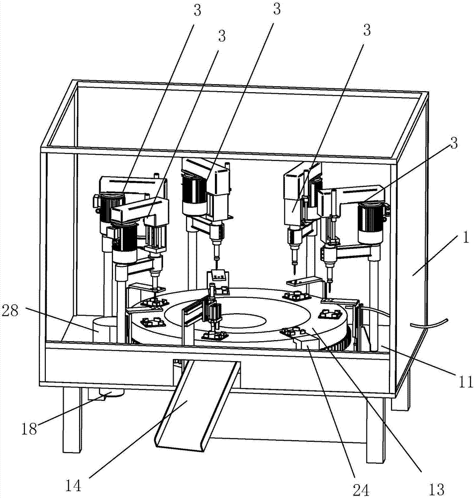
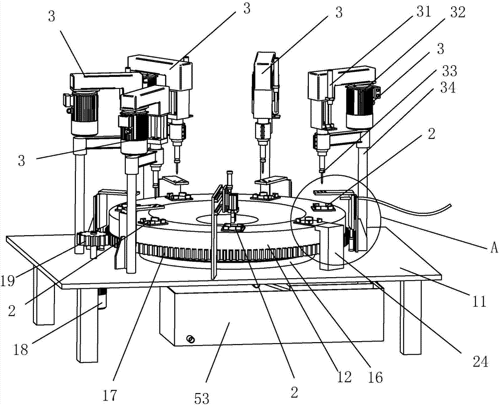
[0035] Embodiment 1: as figure 1 and figure 2 As shown, an automatic precision drilling machine includes a casing 1, and a support plate 11 is arranged inside the casing 1, and the support plate 11 extends along the horizontal direction, and supports the components of the precision drilling machine.

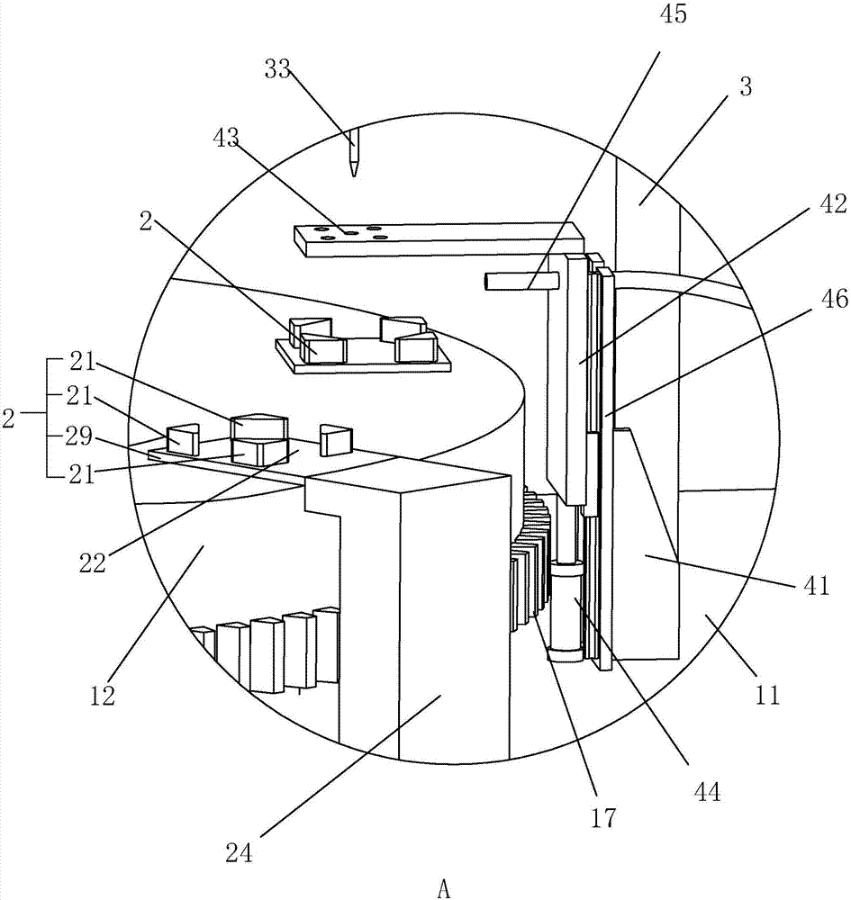
[0036] Such as figure 1 and figure 2 As shown, a working disc 12 is arranged on the surface of the supporting plate 11, and a needle bearing 16 is arranged between the working disc 12 and the supporting plate 11, as Figure 4 As shown, the upper surface of the needle roller bearing 16 is connected to the work disk 12, and the lower surface of the needle roller bearing 16 is connected to the support plate 11, which facilitates the rotational connection between the work disk 12 and the support plate 11, and at the same time the work disk 12 rotates in the horizontal direction of, such as image 3 and Figure 4 As shown, a ring gear 17 is provided on the circumferential side of...

Embodiment 2

[0046] Embodiment 2: An automatic precision drilling machine. The difference between Embodiment 2 and Embodiment 1 is that the cooling water and debris in the mixture are separated in Embodiment 2. In embodiment 2, such as Figure 6 As shown, the collection device 5 below the chip drop hole 15 includes not only the cooling water collection box 53 but also the chip box 55 .

[0047] Such as Figure 6 As shown, the shape of the through hole 51 is a square, the inner side wall of the through hole 51 is provided with a blanking plate 52, the blanking plate 52 is inclined, and the side wall of the blanking plate 52 is welded to the side wall of the through hole 51, The blanking plate 52 is evenly distributed with diversion holes 54. In order to simplify production, the blanking plate 52 can also be made of wire mesh. One end is located below the orthographic projection of the chip drop hole 15, and the area of ​​the blanking plate 52 is greater than the orthographic projection ar...


PUM


Abstract

The invention discloses an automatic fine drilling machine. The automatic fine drilling machine comprises a support plate, a working disc rotating in the horizontal direction is rotatably connected to the support plate, a plurality of clamping bases used for containing objects are arranged on the working disc, the support plate is provided with a driving device used for driving the working disc to rotate and comprises a feeding inlet and a discharging outlet along the rotating track of the working disc, a plurality of drilling stations are arranged between the feeding inlet and the discharging outlet along the rotating track of the working disc, each drilling station corresponds to one clamping base, and the drilling stations machine objects arranged on the clamping bases through the lifting action of drill bits. According to the automatic fine drilling machine, a plurality of the clamping bases are arranged in the circumferential direction of the working disc, multiple objects arranged on the clamping bases can be machined simultaneously in the rotating process of the working disc, therefore, the drilling and machining efficiency is improved, automation, high precision, high reliability, safety, environmental friendliness and energy saving are achieved, and repairing and maintaining are convenient.

Description

technical field [0001] The invention relates to machining drilling equipment, in particular to an automatic precision drilling machine. Background technique [0002] Drilling machine is a general term for machinery and equipment that uses a tool that is harder and sharper than the target to leave a cylindrical hole or hole on the target by means of rotary cutting or rotary extrusion. Also known as drilling rigs, punching machines, drilling machines, through-hole machines, etc. The expected effect is achieved by drilling precision parts. Drilling machines include semi-automatic drilling machines and fully automatic drilling machines. With the increase in human resource costs; most companies consider fully automatic drilling machines as the development direction . [0003] In the prior art, the invention patent with the notification number "CN 204953951U" discloses a device for processing metal plates, which uses a drilling unit with lifting and rotating functions to drill h...

Claims


Application Information

Patent Timeline
IPC IPC(8): B23B39/16B23B47/28B23Q11/10
CPCB23B39/161B23B47/28B23Q11/1069
Inventor 季尧军
Owner 苏州宝罗机械工程有限公司
Learn More