Soil auger

A technology of earth drill and drill bit, which is applied in the direction of sampling device, etc., which can solve the problems of simple connection between drill body and drill bit, inconvenient carrying and operation, and oversized motor earth drill, and achieves low price, time-saving and high-efficiency sampling, Effects that enhance functionality and usability

Inactive Publication Date: 2017-07-14
QINGHAI UNIVERSITY +1
View PDF13 Cites 4 Cited by
  • Summary
  • Abstract
  • Description
  • Claims
  • Application Information

AI Technical Summary

Problems solved by technology

But the drill body and the drill bit of the artificial soil drill in the prior art have a single connection relationship. When this soil drill takes soil, the drill shank pushes the drill rod, and the drill bit goes deep into the soil. It is difficult, time-consuming and labor-intensive, and the work efficiency is low; secondly, when taking the soil, it is necessary to hit the drill pipe with a hammer to provide the power to take the soil. Sampling is particularly laborious
[0004] Although the electric soil drill is less labor-intensive than the artificial soil drill, the cost of the electric soil drill is high, and it is not suitable for wide application; secondly, the electric soil drill is too large, and it is inconvenient to carry and operate when going out.
Therefore, when soil sampling is carried out with the existing soil auger, it brings great difficulties to the work

Method used


Image

  • Soil auger
  • Soil auger
  • Soil auger

Examples


Embodiment 1

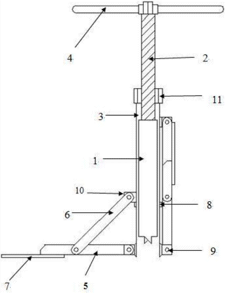
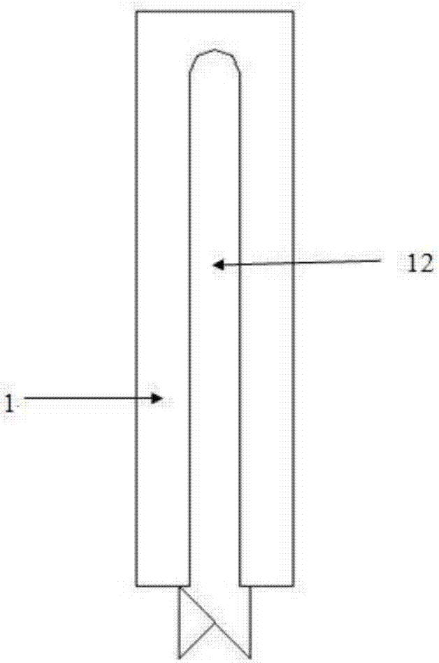
[0036] Such as figure 1 As shown, an earth drill includes a drill bit 1, a screw rod 2, a drill barrel 3, a handle 4, a tie rod 5, a diagonal tie rod 6, a pedal 7, a positioning block 8, a support 9, a slider 10, a nut 11, and an excavation groove. 12. The upper end of the screw 2 is connected to the handle 4, the lower end of the screw 2 is connected to the upper end of the drill bit 1, the screw 2 is provided with an external thread matching the internal thread of the nut 11, and the nut 11 is threaded on the screw 2.

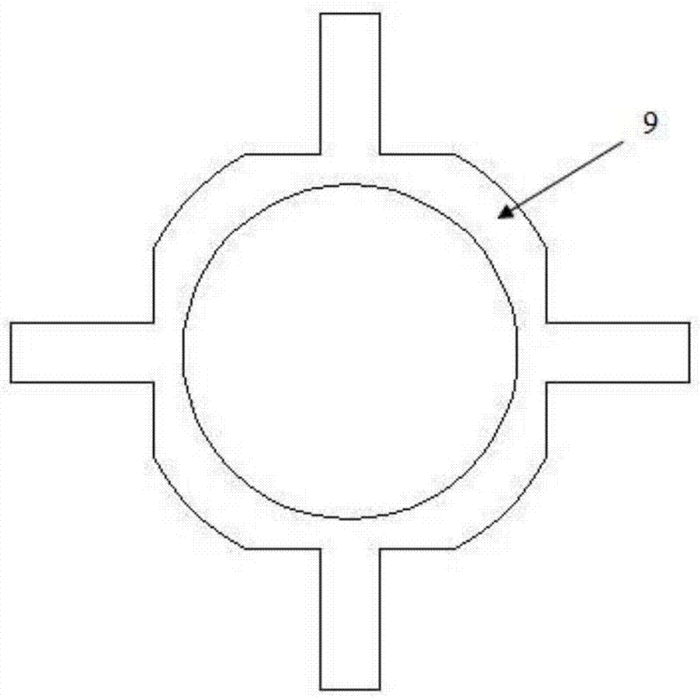
[0037] The upper end of the drill tube 3 is connected with the nut 11, the lower end of the drill tube 3 is welded with a support 9, and the drill bit 1 is placed in the drill tube 3.

[0038] Such as figure 1 As shown, one end of the tie rod 5 is welded and fixed on the support 9, and the other end of the tie rod 5 is connected to the pedal 7; one end of the tie rod 6 is connected to the middle position of the tie rod 5, and the other end of the tie rod 6 p...

Embodiment 2

[0047] In this embodiment, the screw rod and the drill bit are pin-connected with a detachable device, and the drill bit can be disassembled and replaced during operation.

[0048] Such as figure 1 As shown, an earth drill includes a drill bit 1, a screw rod 2, a drill barrel 3, a handle 4, a tie rod 5, a diagonal tie rod 6, a pedal 7, a positioning block 8, a support 9, a slider 10, a nut 11, and an excavation groove. 12. The upper end of the screw 2 is connected to the handle 4, the lower end of the screw 2 is connected to the upper end of the drill bit 1, the screw 2 is provided with an external thread matching the internal thread of the nut 11, and the nut 11 is threaded on the screw 2.

[0049] The upper end of the drill tube 3 is connected with the nut 11, the lower end of the drill tube 3 is welded with a support 9, and the drill bit 1 is placed in the drill tube 3.

[0050] Such as figure 1 As shown, one end of the tie rod 5 is welded and fixed on the support 9, and ...

Embodiment 3

[0059] In this embodiment, the drill barrel and the nut are connected together in a detachable manner, and the direction of the drill body can be disassembled and replaced during operations.

[0060] Such as figure 1 As shown, an earth drill includes a drill bit 1, a screw rod 2, a drill barrel 3, a handle 4, a tie rod 5, a diagonal tie rod 6, a pedal 7, a positioning block 8, a support 9, a slider 10, a nut 11, and an excavation groove. 12; The upper end of the screw rod 2 is connected to the handle 4, and the lower end of the screw rod 2 is connected to the upper end of the drill bit 1; the drill bit 1 is placed in the drill barrel 3.

[0061] The upper end nut 11 of the drill tube 3 is connected in a detachable manner, the lower end of the drill tube 3 is welded with a support 9, and the drill bit 1 is placed in the drill tube 3 .

[0062] Such as figure 1 As shown, one end of the tie rod 5 is welded and fixed on the support 9, and the other end of the tie rod 5 is connec...


PUM

PropertyMeasurementUnit
angleaaaaaaaaaa

Abstract

A soil auger belongs to the technical field of soil appliance and is applied in soil sampling. The soil auger comprises a drill, a screw, a drill barrel, a handle, a transverse tie rod, a diagonal tie rod, a pedal, a slide block, a support and a soil outlet groove. The upper end of the screw is connected to the handle, and the lower end of the screw is connected to the upper end of the drill. The screw is provided with external thread which matches internal thread of a nut, which is in threaded connection to the screw. The upper end of the drill barrel is connected to the nut. The support is welded at the lower end of the drill barrel. The drill is arranged inside the drill barrel. One end of the transverse tie rod is fixed on the support through welding, and the other end of the transverse tie rod is connected to the pedal. One end of the diagonal tie rod is connected to the middle position of the transverse tie rod, and the other end of the diagonal tie rod is connected to the drill barrel through the slide block. The transverse tie rod, the diagonal tie rod and the pedal form a foldable pedal device. The soil auger of the invention is convenient for dismounting and replacement of the drill and the drill body. The function and practicality of the soil auger are enhanced. The soil auger is reasonably designed, is easy to carry, is time-saving and labor-saving to operate, is convenient for soil sampling, and is convenient for promotion and application.

Description

technical field [0001] The invention belongs to the technical field of soil tools, and in particular relates to a soil drill. Background technique [0002] In the research of ecology and soil science, the collection and analysis of soil is of great significance. When carrying out agricultural production, soil pollution control, animal and plant research, etc., it is often necessary to sample field soil. The most basic tool for these tasks is the soil auger. [0003] At present, existing soil drills are usually artificial soil drills and electric motor soil drills. But the drill body and drill bit of the artificial soil drill in the prior art have a single connection relationship. When this soil drill takes soil, the drill shank pushes the drill rod, and the drill bit goes deep into the soil. It is difficult, time-consuming and labor-intensive, and the work efficiency is low; secondly, when taking soil, it is necessary to hit the drill pipe with a hammer to provide the power...

Claims


Application Information

Patent Timeline
Patent Type & Authority Applications(China)
IPC IPC(8): G01N1/08
CPCG01N1/08
Inventor 王小红徐成体张发廷高莉王宏生德科加
Owner QINGHAI UNIVERSITY
Why Eureka
Try Eureka