Device for peeling off sheath of optical cable and application method of device

An optical cable and sheath technology, which is applied in the field of precise exploitation devices for optical cable sheaths, can solve the problems of laborious hand cranking, complicated assembly, and large friction between the optical cable and the outer peripheral surface of a rolling wheel, etc., and achieves the effect of reducing pulling resistance and easy operation.

Active Publication Date: 2017-07-14
PINGDINGSHAN POWER SUPPLY ELECTRIC POWER OF HENAN +1
View PDF11 Cites 4 Cited by
  • Summary
  • Abstract
  • Description
  • Claims
  • Application Information

AI Technical Summary

Problems solved by technology

At the same time, the stripping tool also has the following problems: in the process of pulling the cable to be stripped and passing through the ring fixing frame, even if the contact surface between the cable support mechanism and the cable is a smooth surface, due to the gap between the cable and the cable support mechanism The contact surface between them is relatively large, and the continuous friction and heat generation will limit the continuous working time of the exploiting device; and because the blade and the blade adjustment device are fixed or rotationally connected, it is difficult for the blade adjustment device to ensure that the blade is in the process of adjustment. Without deflection, it is difficult to achieve precise control of the cutting depth of the blade
However, the optical cable stripping device also has the following problems: complex structure, cumbersome assembly, high electric peeling cost, large device volume, heavy weight, and regular maintenance; when the manual peeling is performed, the friction force between the cable and the outer peripheral surface of the rolling wheel is large. It is very laborious; the knife feed device used in this invention uses the principle of threading to control the knife to realize the cutting of the optical cable sheath, the operation process is cumbersome, the factors affecting the accuracy of the depth of the knife increase, and the control difficulty increases; and the optical cable used in the invention is fastened The mechanism is clamped on the outer surface of the optical cable, and the contact surface is large. When the optical cable is transmitted to a certain direction with the rotation of the rolling wheel, the resistance is large, and the manual operation is laborious. The electric drive increases the cost and is not conducive to the long-term continuous operation of the device.

Method used


Image

  • Device for peeling off sheath of optical cable and application method of device
  • Device for peeling off sheath of optical cable and application method of device
  • Device for peeling off sheath of optical cable and application method of device

Examples


Embodiment 2

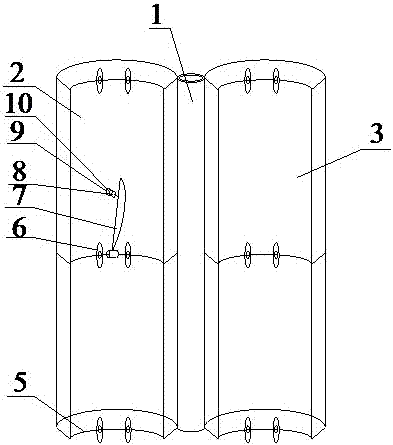
[0057] refer to image 3 and Figure 6 , the precise stripping device for the optical cable sheath described in this embodiment is different from Embodiment 1 in that:

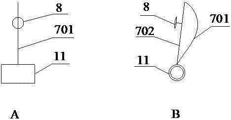
[0058] A skinning knife 7 is respectively arranged on the wheel shaft in the middle of the first arc-shaped cylinder 2 and the second arc-shaped cylinder 3, the bottom end of the skinning knife is rotatably connected with the wheel shaft, and the blade 701 of the skinning knife is vertically facing For the optical cable to be stripped, the blade back 702 of the stripping knife is provided with a back iron 8 .

[0059] In this embodiment, the number of stripping knives is 2, and they are respectively located on the axles in the middle of the first arc-shaped tube 2 and the second arc-shaped tube 3. At this time, one stripping operation can form two strips on the same optical cable sheath. Cutting the line, the outer skin is divided into two pieces, and the manual peeling is easier and labor-saving.

[0060] ...


PUM


Abstract

The invention discloses a device for peeling off the sheath of an optical cable and an application method of the device, and belongs to the technical field of power cable peeling tools. The device comprises a rotating shaft, a first arc-shaped barrel, and a second arc-shaped barrel, wherein the first and second arc-shaped barrels are connected with the rotating shaft. The inner sides of the first and second arc-shaped barrels are respectively provided with three or more wheel axles in the length direction, wherein each wheel axle is provided with two rolling wheels. The wheel axle(s) located at the central part of the first arc-shaped barrel and/or the second arc-shaped barrel are/is provided with a plurality of peeling cutters. The bottoms of the peeling cutters are rotatingly connected with the wheel axles, and the edges of the peeling cutters are perpendicular to a to-be-peeled optical cable. The backs of the peeling cutters are provided with back irons. The first arc-shaped barrel and/or the second arc-shaped barrel are/is provided with through holes which are in threaded connection with magnetic fine tuning parts, wherein the magnetic fine tuning parts attract the back irons. The device is novel in structure, is reasonable in design, is small in size, is light in weight, is portable, is flexible for use, is small in peeling resistance, and facilitates the precise control of the cutting depth of the peeling cutters.

Description

technical field [0001] The invention belongs to the technical field of power cable stripping tools, and in particular relates to a precise stripping device for an optical cable sheath and a method for using the same. Background technique [0002] In recent years, with the rapid development of smart grid, more and more new smart substations have been built. Inside the smart substation, the signal is mainly transmitted in the optical fiber in the form of optical signal, and each interval has multiple optical cables. During the construction of the substation, the outer sheath of the optical cable needs to be stripped first, and then the inner fiber core can be fused. There is no special stripping tool for the outer sheath of the optical cable. The traditional method is to use a stripping knife to peel off a trace at the place where the outer sheath of the optical cable needs to be stripped, exposing a fracture of the outer sheath of the optical cable, and then pull the outer s...

Claims


Application Information

Patent Timeline
Patent Type & Authority Applications(China)
IPC IPC(8): G02B6/245
CPCG02B6/245Y02W30/82
Inventor 马文恒胡军台郭毅鹏付晓王逸超赵建军张磊刑文涛王山虎李鹏远
Owner PINGDINGSHAN POWER SUPPLY ELECTRIC POWER OF HENAN
Why Eureka
Try Eureka