
Novel multi-effect outer wall air inlet pipe and use method thereof

A multi-effect, air inlet duct technology, applied in rigid pipes, pipes, pipe elements, etc., can solve the problem of damaging the inner wall decoration layer and wall structure layer, affecting the living or working environment of people, and affecting the normal operation of ventilation equipment. and other problems, to achieve the effect of quick installation, avoiding the intrusion of water into the wall and the invasion of mosquitoes, and the best anti-corrosion effect.

Inactive Publication Date: 2017-07-18
KUNSHAN SILAIMU ENERGY SAVING TECH CO LTD
View PDF8 Cites 4 Cited by
  • Summary
  • Abstract
  • Description
  • Claims
  • Application Information

AI Technical Summary

Problems solved by technology

[0003] However, when this type of air duct is in use, it is easy to generate noise in the pipe, which affects the living or working environment of people; and after the air duct is used for a long time due to the aging of the outer wall of the pipe, it is easy to cause the intrusion of external rainwater or humid air. If things go on like this, rainwater or Moist air will seep into the inner wall of the wall, destroying the decorative layer of the inner wall and the structural layer of the wall; in addition, although the outer ends of some ventilation ducts are equipped with rain-proof covers, the rain will still flow when the wind is heavy and the rain is heavy. Into the ventilation duct, causing water accumulation or even backflow, affecting the normal operation of the ventilation equipment

Method used


Image

  • Novel multi-effect outer wall air inlet pipe and use method thereof
  • Novel multi-effect outer wall air inlet pipe and use method thereof
  • Novel multi-effect outer wall air inlet pipe and use method thereof

Examples


Embodiment

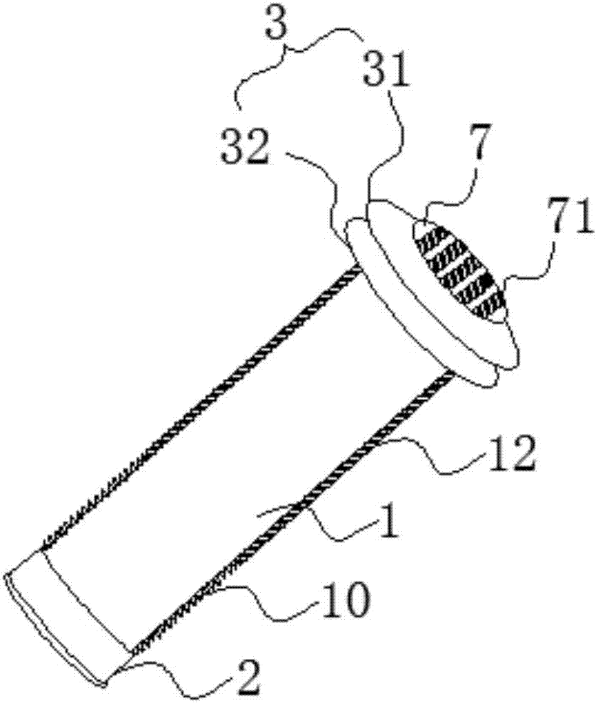
[0053] Embodiment: a kind of novel multi-effect exterior wall air intake pipe, such as Figure 1-10 As shown, it includes a pipe body 1, a positioning flange 2 and a sealing ring 3. The positioning flange 2 and the sealing ring 3 are respectively located at both ends of the pipe body 1. The pipe body 1 and the positioning method A telescopic flexible hose 10 is also included between the flanges 2, the front end of the flexible hose 10 is fixedly connected to the rear end of the pipe body 1, and the rear end of the flexible hose 10 is connected to the positioning flange 2 fixed connection;

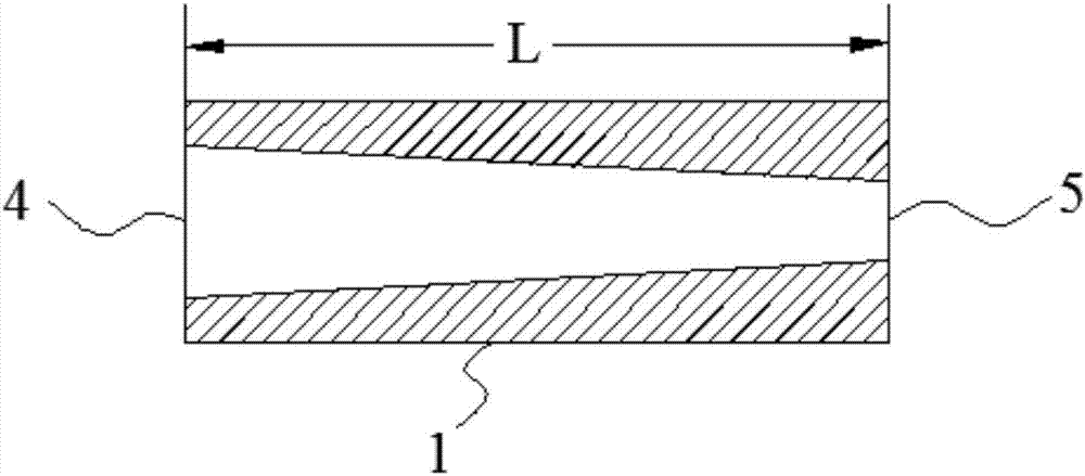
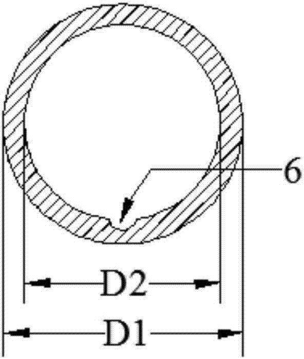
[0054] The inner pipe wall of the pipe body 1 is a pipe wall of different diameters tapered from the air inlet 4 to the air outlet 5, the outer diameter D1 of the pipe body is 8-10cm, and the inner diameter D2 of the air inlet of the pipe body is 6-7cm, the inner diameter D3 of the air outlet of the pipe body is 4-5cm; on the inner pipe wall of the pipe body 1 and in the middle of the bott...


PUM


Abstract

The invention discloses a novel multi-effect outer wall air inlet pipe comprising a pipe body, a positioning flange and a seal ring. A telescopic flexible hose is arranged between the pipe body and the positioning flange. The inner pipe wall of the pipe body is a reducing pipe wall. Multiple silencing holes are evenly distributed in the inner wall pipe and are filled with silencing cotton. A grating piece is arranged at an air inlet. The rear end of the grating piece is connected with the air inlet in a threaded manner. Three to five inclined blades are arranged at the front end of the grating piece. A first roughening ring and a second roughening ring are arranged on the outer surface of the pipe body. A protection layer is arranged on the outer wall of the pipe body and comprises a nanometer anti-corrosion coating, a heat preservation layer and an anti-corrosion waterproof coating. By means of the novel multi-effect outer wall air inlet pipe, noise generated when air enters the pipe body can be reduced; the protection layer is arranged, the corrosion prevention function, the heat preservation function and the waterproof function of the outer wall of the pipe body are improved, the effects of slowing down aging of the outer wall of the pipe body and reducing rainwater invasion are achieved, and the service life of the air inlet pipe can be prolonged; and backward pouring of rainwater or invasion of mosquitoes can be prevented, accumulation of foreign matter in the pipe body can be avoided, and maintenance of the interior of the pipe body in the later period can be reduced.

Description

technical field [0001] The invention belongs to the technical field of building air ducts, in particular to a novel multi-effect external wall air inlet duct. Background technique [0002] Some ventilating equipment used in households, such as air purifiers, air conditioners, etc., need to punch holes on the wall near the placement position before installing the ventilation ducts. During installation, the fixing of the outside of the ventilation duct requires the operator to operate outdoors. In order to ensure the safety of the work, the operator needs to take safety measures before proceeding. However, for the installation of some high-rise buildings, there are still certain safety hazards for the operator. affect its work efficiency. Therefore, someone in the industry has developed an air duct that does not require outdoor installation. The entire installation process can be carried out directly indoors, which is easy to operate and reduces potential safety hazards. [...

Claims


Application Information

Patent Timeline
Patent Type & Authority Applications(China)
IPC IPC(8): F16L27/12F16L9/21F16L5/02F16L55/07F16L9/14F16L58/04F16L59/02
CPCF16L5/02F16L9/14F16L9/21F16L27/12F16L55/07F16L58/04F16L59/02
Inventor 戴文朱蓓蕾管正刚
Owner KUNSHAN SILAIMU ENERGY SAVING TECH CO LTD
Learn More