Protection circuits and electronic equipment

A technology for protecting circuits and circuits, applied in the direction of emergency protection circuit devices, circuits, circuit devices, etc., can solve the problems of non-disclosure, etc., and achieve the effect of a simple structure

Active Publication Date: 2020-06-16
TIANMA MICRO ELECTRONICS CO LTD
View PDF9 Cites 0 Cited by
  • Summary
  • Abstract
  • Description
  • Claims
  • Application Information

AI Technical Summary

Problems solved by technology

Patent Document 4 does not disclose a method of arbitrarily controlling the threshold voltages of the bottom gate and the top gate

Method used


Image

  • Protection circuits and electronic equipment
  • Protection circuits and electronic equipment
  • Protection circuits and electronic equipment

Examples


no. 1 approach

[0033] Hereinafter, a first embodiment will be described.

[0034] In the specification and claims, serial numbers such as "first", "second", and "third" are given to clarify the relationship between elements and prevent confusion between elements. Therefore, these serial numbers do not limit the number of elements.

[0035] In addition, "connection" means electrical connection between connection objects. "Electrical connection" includes connection between connected objects via electrical elements such as electrodes, wiring, resistors, and capacitors. "Electrode" or "wiring" does not functionally limit these components. For example, "wiring" may be used as a part of "electrode", and conversely, "electrode" may be used as a part of "wiring".

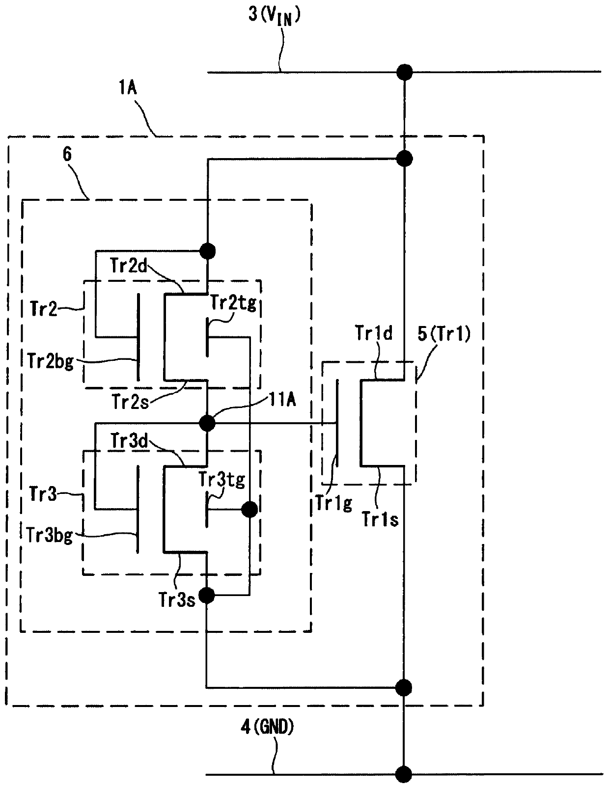
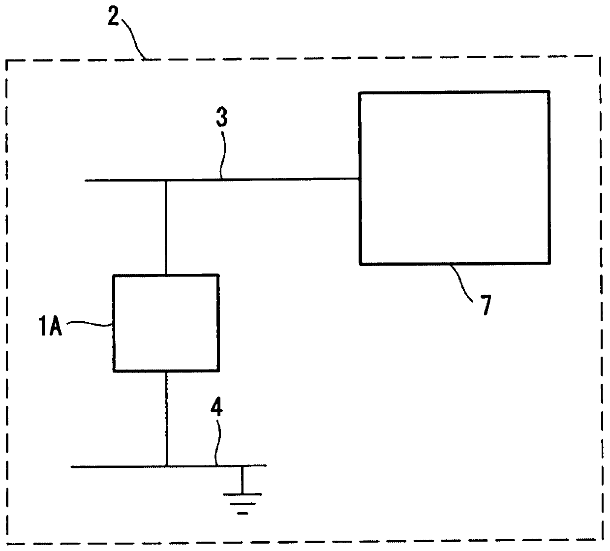
[0036] figure 1 is a circuit diagram showing the configuration of the protection circuit 1A according to the present embodiment. figure 2 is a circuit diagram showing the configuration of an electronic device including the protecti...

no. 2 approach

[0091] Hereinafter, a second embodiment will be described. Figure 6 It is a circuit diagram showing the structure of the protection circuit 1B according to this embodiment. exist Figure 6 in, with figure 1 The same components are used as figure 1 The same reference numerals are assigned to the same reference numerals, and descriptions thereof will not be repeated.

[0092] The control circuit 5 provided in the protection circuit 1B further includes a thin film transistor Tr4 connected in parallel to the thin film transistor Tr1 . The thin film transistor Tr4 also controls the line current. Here, when a negative overvoltage is applied to the first wiring 3, current flows from the second wiring 4 to the first wiring 3, and the thin film transistor Tr4 operates to protect the object to be protected from the overvoltage.

[0093] The thin film transistor Tr4 has a second electrode Tr4 s connected to the first wiring 3 and a first electrode Tr4 d connected to the second wi...


PUM


Abstract

The invention relates to protection circuits and electronic equipment. The present invention provides a protection circuit capable of appropriately controlling an operating voltage with a simple structure. The protection circuit includes: a control circuit that controls current between the first wiring and the second wiring; and an application circuit that applies a voltage to the control circuit. The control circuit includes a first thin film transistor to control current. The applying circuit includes a second thin film transistor and a third thin film transistor connected in series. Both the second thin film transistor and the third thin film transistor include a first gate and a second gate. The first gate of the second thin film transistor is connected to the first wiring. The first gate of the third thin film transistor is connected to a connection point between the second thin film transistor and the third thin film transistor. The second gate of the second thin film transistor and the second gate of the third thin film transistor are connected to the second wiring. The application circuit applies the voltage at the connection point to the gate of the first thin film transistor.

Description

[0001] Cross References to Related Applications [0002] This application claims priority to Patent Application No. 2015-208884 filed in Japan on October 23, 2015, which is incorporated herein by reference in its entirety. technical field [0003] The invention relates to protection circuits and electronic equipment. Background technique [0004] Electronic equipment such as a liquid crystal display device is provided with a protection circuit that protects the electronic equipment from overvoltage caused by, for example, static electricity. The protection circuit is provided between, for example, a signal line connected to an electronic device and a ground line, and when an overvoltage is applied to the signal line, a current flows to the ground line, thereby protecting the electronic device. [0005] As the protection circuit, a circuit having a structure in which source electrodes and drain electrodes of two thin film transistors (TFTs) are connected in parallel or in s...

Claims


Application Information

Patent Timeline
Patent Type & Authority Patents(China)
IPC IPC(8): G09G3/36
CPCG09G3/36G09G2330/04G09G3/20G09G2330/025H01L27/0266H01L27/124H01L29/7869H02H9/045
Inventor 关根裕之山本祐辅
Owner TIANMA MICRO ELECTRONICS CO LTD
Why Eureka
Try Eureka