Ball head milling cutter for splicing die milling

A technology of splicing molds and ball-end milling cutters, applied in milling cutters, manufacturing tools, milling machine equipment, etc., can solve the problems of poor machining quality, tool wear, and large cutting force, and achieve improved stability, less vibration, and avoidance of cutting edges. damage effect

Inactive Publication Date: 2017-07-21
HARBIN UNIV OF SCI & TECH
View PDF8 Cites 6 Cited by
  • Summary
  • Abstract
  • Description
  • Claims
  • Application Information

AI Technical Summary

Problems solved by technology

[0004] The invention provides a ball end milling cutter for splicing mold milling to solve the problems of the existing indexable milling cutters with large cutting force and large vibration during cutting, resulting in serious tool wear and poor processing quality.

Method used


Image

  • Ball head milling cutter for splicing die milling
  • Ball head milling cutter for splicing die milling
  • Ball head milling cutter for splicing die milling

Examples


Embodiment Construction

[0025] The present invention will be further described below in conjunction with the accompanying drawings and through specific embodiments.

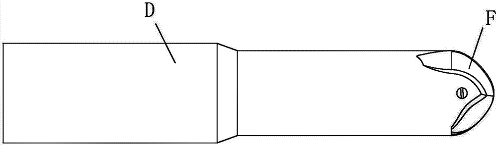
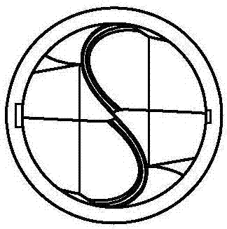
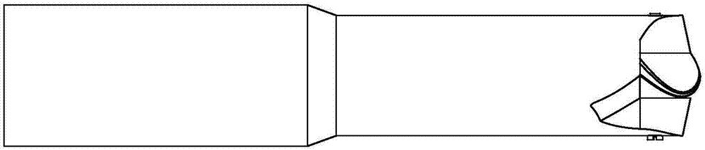
[0026] see Figure 1 to Figure 10 Description, a ball end milling cutter for splicing mold milling, which includes a cutter bar D and a cutter body F, the cutter bar D is connected to the cutter body F; the cutter body F has a helical cutting edge;

[0027] The cutting edges are respectively cutting edge one 1 and cutting edge two 15;

[0028] Both sides of the cutting edge-1 have a rake face-6, a first flank face-3 and a second flank face-4;

[0029] Both sides of the cutting edge 15 have a rake face 2 17, a first flank face 13 and a second flank face 12;

[0030] The upper surface 10 of the cutter body F is respectively connected with the main groove curved surface 1 and the secondary groove curved surface 11, and the transition part between the rake surface 1 6 and the main groove curved surface 1 is a chip flute 7, The secondary ...


PUM


Abstract

The invention relates to a ball head milling cutter, in particular to a ball head milling cutter for splicing die milling so as to solve the problems that in the cutting process, an existing rotary milling cutter is large in cutting force and large in vibration, consequently, the cutter is seriously abraded, and the machining quality is poor. A body is provided with spiral cutting blades. A front cutter face 1, a first rear cutter face 1 and a second rear cutter face 1 are arranged on the two sides of a first cutting blade. A front cutter face 2, a first rear cutter face 2 and a second rear cutter face 2 are arranged on the two sides of a second cutting blade. The upper surface of the body is connected with a first main groove hook face and a second auxiliary groove hook face. A transition part of the front cutter face 1 and the first main groove hook face is a first scrap containing groove, and the second auxiliary groove hook face is connected with the second rear cutter face 2. The lower surface of the body is connected with a second main groove hook face and a first auxiliary groove hook face, the transition part of the front cutter face 2 and the second main groove hook face is a second scrap containing groove, and the first auxiliary groove hook face is connected with the second rear cutter face 1. The ball head milling cutter is used for milled piece machining.

Description

technical field [0001] The invention relates to a ball-end milling cutter, in particular to a ball-end milling cutter for splicing mold milling, in particular to a helical-blade ball-end milling cutter with an impact resistance and wear resistance for processing splicing molds. Background technique [0002] The ball end milling cutter is a tool with a blade similar to a ball end and assembled on a milling machine for milling various curved surfaces and arc grooves. Ball end milling cutter is also called R cutter. Ball end milling cutter can work normally in high temperature environment. Ball nose milling cutters can be used in various industries. [0003] At present, a kind of integral ball end milling cutter is mostly used in the finishing of splicing molds for automobile panels. During the process of processing splicing parts, the milling processing characteristics in the splicing transition zone are complicated, and the wear and damage of the cutting tools are serious. ...

Claims


Application Information

Patent Timeline
Patent Type & Authority Applications(China)
IPC IPC(8): B23C5/10
CPCB23C5/1027
Inventor 岳彩旭刘俊严复钢
Owner HARBIN UNIV OF SCI & TECH
Why Eureka
Try Eureka