Manual composite blanking die

A punching die and concave die technology, which is applied in the field of manual compound punching dies and punching dies, can solve the problems of increasing production costs, manual processing, and low work efficiency, and achieve the goals of improving work efficiency, reducing procedures, and saving costs Effect

Inactive Publication Date: 2017-07-21
XUZHOU TIANLI DIE MFG
View PDF0 Cites 5 Cited by
  • Summary
  • Abstract
  • Description
  • Claims
  • Application Information

AI Technical Summary

Problems solved by technology

Blanking dies are divided into simple punching dies, continuous punching dies and composite punching dies according to the process and degree of combination. Simple punching dies can only complete one process of punching or blanking in sequence, and the work efficiency is low; continuous punching According to a certain sequence, the punching die is a punching die that completes the two processes of punching and blanking at different positions of the mold in the sequence of the slider of the punching machine; the composite punching die is in a stroke of the slider At the same time, the punching and blanking are completed on the same station of the die, so the composite punching die can punch some complex workpieces with high precision requirements, but when the existing composite punching die pair punches thin plates, they need to cooperate When the press is used for stamping work, manual processing is required when discharging waste materials, which has a low safety factor; when a large number of small workpieces are punched, there is no need for a lot of pressure, and the use of a press is expensive and increases production costs.

Method used


Image

  • Manual composite blanking die
  • Manual composite blanking die
  • Manual composite blanking die

Examples


Embodiment Construction

[0013] The present invention will be further described below in conjunction with accompanying drawing.

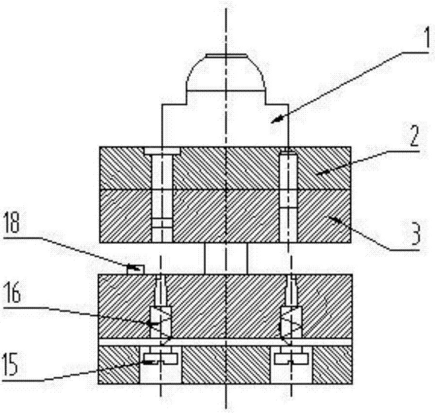
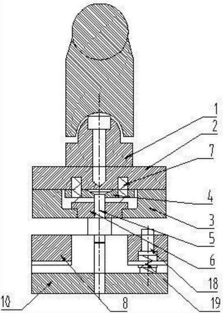
[0014] Such as Figure 1 to Figure 3 Shown, a kind of manual composite blanking die, comprises upper mold and lower mold, also comprises manual pressure bar, and described upper mold comprises handle mold 1, top plate 2, die 3, punch fixing plate 4, and described top plate 2 It is connected with the punch fixing plate 4 by screws, the top plate 2 and the die 3 are connected by cylindrical pins, the punch 5 is embedded on the punch fixing plate 4, the ejector 6 is in clearance fit with the die 3, the ejector 6, the die A compression spring 7 is arranged between the mold 3 and the punch fixing plate 4; the lower mold includes a stripping plate 8, a convex and concave die 9 and a bottom plate 10, and the convex and concave mold 9 is fixed on the bottom plate 10 by screws, and the stripping plate 8 passes through The screw 15 and the compression spring 2 16 are connected on th...


PUM


Abstract

The invention discloses a manual compound blanking die, wherein the upper die includes a handle die, a top plate, a die, and a punch fixing plate, the top plate, the punch fixing plate, and the die are integrated, and the punch is embedded in the punch fixing plate. The ejector is matched with the die, and a compression spring is arranged between the ejector, the die and the punch fixing plate; the lower die includes a stripping plate, a convex and concave die and a bottom plate, and the convex and concave dies are fixed on the bottom plate by screws , the stripping plate is connected to the bottom plate through screws and compression springs, and the gap between the stripping plate and the punch and die is matched; there is a guide post between the die and the bottom plate, and the pressure hand lever includes a lever and a support seat, and one end of the lever is hinged On the support base, a pressure sleeve is fixed in the middle of the lever, the inside of the pressure sleeve is a concave spherical surface, and the top of the handle mold is a convex spherical surface that cooperates with the pressure sleeve. The invention can reduce working procedures, greatly improve work efficiency, reduce loss of raw materials, save cost, and both the inner hole and the edge of the blanking piece can achieve higher precision.

Description

technical field [0001] The invention relates to a blanking die, in particular to a manual compound blanking die, which belongs to the technical field of stamping equipment. Background technique [0002] The blanking die is mainly used for blanking and punching of various plates. The working part of the die is the cutting edge of the convex and concave dies. When the cutting edge is working, it bears impact force, shear force, bending force, and strong shearing force friction. Blanking dies are divided into simple punching dies, continuous punching dies and composite punching dies according to the process and degree of combination. Simple punching dies can only complete one process of punching or blanking in sequence, and the work efficiency is low; continuous punching According to a certain sequence, the punching die is a punching die that completes the two processes of punching and blanking at different positions of the mold in the sequence of the slider of the punching ma...

Claims


Application Information

Patent Timeline
IPC IPC(8): B26F1/44B26F1/40B26F1/14B26F1/02B26D7/18
CPCB26F1/44B26D7/1818B26F1/02B26F1/14B26F1/40
Inventor 董长刚
Owner XUZHOU TIANLI DIE MFG
Why Eureka
Try Eureka