Stack-up type feeding device and operating method thereof

A feeder and stacking technology, which is applied in the direction of unstacking, transportation and packaging of objects, can solve the problems of high manufacturing cost and complicated mechanical structure, and achieve the effect of low production cost, simple working method and low production cost

Active Publication Date: 2017-07-21
GUANGDONG TUODI INTELLIGENT TECH
View PDF5 Cites 5 Cited by
  • Summary
  • Abstract
  • Description
  • Claims
  • Application Information

AI Technical Summary

Problems solved by technology

[0002] Many existing industrial processes use automated production lines. Automatic feeding equipment is essential in automated production lines, especially automatic feeding equipment is very common. Many production lines use industrial robots to achieve automatic feeding, but these automatic feeding The mechanical structure of the equipment is complex and the manufacturing cost is high

Method used


Image

  • Stack-up type feeding device and operating method thereof
  • Stack-up type feeding device and operating method thereof
  • Stack-up type feeding device and operating method thereof

Examples


Embodiment 1

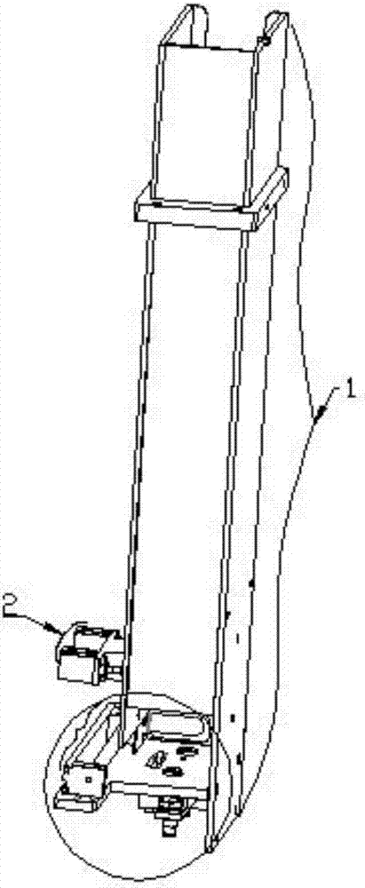
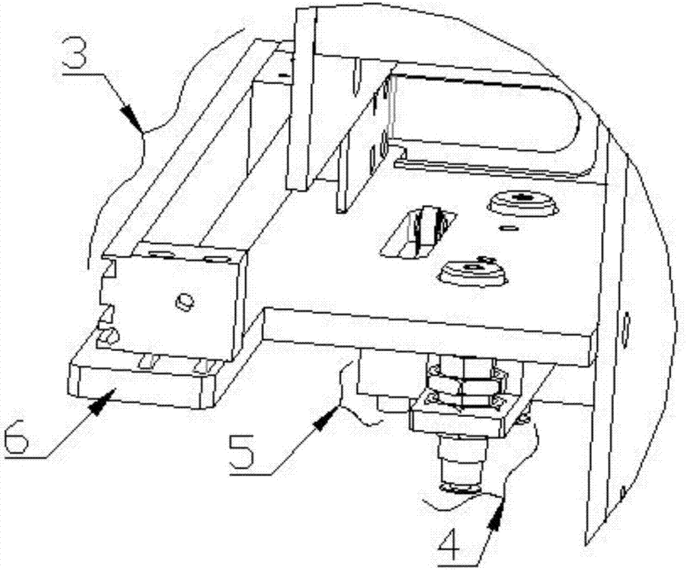
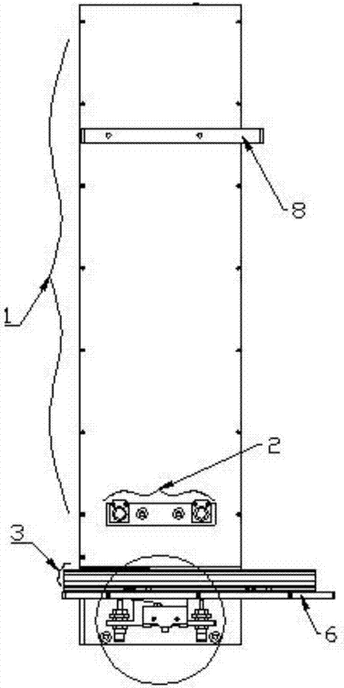
[0070] Embodiment one, such as Figure 1-13 , a stacked feeding machine, including the lower bin 1, and also includes a U-shaped frame 8, the U-shaped frame 8 is stuck above the lower bin 1 and fixed with bolts, and the inside of the lower bin 1 is placed Box-shaped material 7, the front of the lower material bin 1 is provided with a side clamping mechanism 2 close to the bottom, and the bottom of the lower material bin 1 is provided with a feeding device, and the feeding device includes a feeding device connected to the lower end of the lower material bin 1. plate 6, the feeding plate 6 protrudes from the conveying plate directly in front of the downward hopper 1, the conveying mechanism 3 is fixed above the conveying plate, and the ejecting mechanism 4 and the sensor 5 are fixed below the feeding plate 6 The lower silo 1 includes a front panel 101, a back panel 102, a left side panel 103 and a right side panel 104 connected together by screws and the upper ends are flush. S...

Embodiment 2

[0071] Embodiment two, such as Figure 1-13 , is basically the same as the first embodiment. Preferably, the sensor 5 includes a main body 501, a spring 502 and a contact 503 located below the spring 502 are arranged above the main body 501, and a roller 504 is provided at the end of the spring 502. , the feeding plate 6 is provided with a rectangular notch above the shrapnel 502, the roller 504 passes through the rectangular notch, the main body 501 includes a pressure sensor connected to the contact 503 and a contact rotary speed sensor connected to the roller 504 ; Main body 501, shrapnel 502, contact 503, roller 504 these 4 parts together form a limit switch with roller, namely inductor 5; The friction force by which the small material box is pushed out from the silo.

Embodiment 3

[0072] Embodiment three, such as Figure 1-13 , basically the same as the second embodiment, preferably, the side clamp drive 202 and the ejector drive 402 are both telescopic cylinders with electromagnetic reversing valves, and both the clamping rod and the ejector rod are the piston rods of the telescopic cylinder , the conveying drive 301 is a magnetically coupled cylinder with an electromagnetic reversing valve, the inside of the guide rod 303 is a piston rod with a magnetic ring armor, and the slider 304 is provided with a sleeve hole, and the inside of the sleeve hole A magnetic ring B that is magnetically opposite to the magnetic ring A is fixed, and the slider 304 is sleeved on the guide rod 303 through the magnetic ring B.


PUM


Abstract

The invention provides a stack-up feeding device and an operating method of the stack-up type feeding device. The stack-up type feeding device comprises a discharging bin and further comprises a U-shaped frame. The U-shaped frame is clamped to the portion above the discharging bin and fixed through bolts. A box-shaped material is put into the discharging bin. A side clamping mechanism close to the bottom is arranged on the front face of the discharging bin. A feeding device is arranged on the bottom portion of the discharging bin. The feeding device comprises a feeding plate connected to the lower end of the discharging bin. The feeding plate extends straight out of a conveying plate in the direction of the discharging bin. A conveying mechanism is fixedly arranged above the conveying plate. A material jacking mechanism and a sensor are fixedly arranged below the feeding plate. The stack-up type feeding device is simple in structure and low in manufacturing cost and is simple in operating method, easy to operate and low in production cost, the sensor is reasonably used, and the automatic feeding is achieved.

Description

technical field [0001] The invention belongs to the technical field of automatic feeding, and in particular relates to a stacked feeding machine and its working method. Background technique [0002] Many existing industrial processes use automated production lines. Automatic feeding equipment is essential in automated production lines, especially automatic feeding equipment is very common. Many production lines use industrial robots to achieve automatic feeding, but these automatic feeding The mechanical structure of the equipment is complex and the manufacturing cost is high. Contents of the invention [0003] In order to solve the above technical problems, the present invention provides a stacked feeder and its working method. [0004] The technical solution of the present invention is: a stacked feeding machine, including a lower hopper, and a U-shaped frame, the U-shaped frame is stuck above the lower hopper and fixed with bolts, and the inside of the lower hopper is ...

Claims


Application Information

Patent Timeline
Patent Type & Authority Applications(China)
IPC IPC(8): B65G59/06
CPCB65G59/067
Inventor 潘小明郭春良
Owner GUANGDONG TUODI INTELLIGENT TECH
Why Eureka
Try Eureka